- Phone
-
Address
Guoqing Village, Ma'an Town, Keqiao District, Shaoxing City
Product Categories
Shaoxing Dongya Packaging Machinery Factory
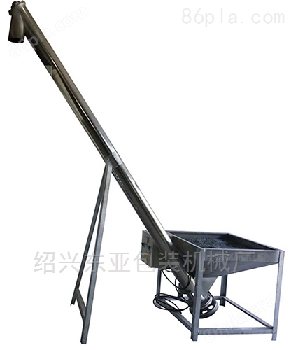
Stainless steel open spiral feeding machine
NegotiableUpdate on 01/17
- Model
- Nature of the Manufacturer
- Producers
- Product Category
- Place of Origin
Overview
The stainless steel open spiral feeding machine is designed and manufactured specifically for the plastic and powder production and processing industries. All parts of the machine that come into contact with materials are made of stainless steel; Can be used in conjunction with various specifications of extruders, high-speed mixers, and plastic mixers; Widely applicable for the loading (feeding) of various powder, granular, recycled and crushed materials.
Product Details
Stainless steel open spiral feeding machineoperation
1. Turn on the power switches for the feeding motor and vibration motor. This switch is a universal conversion switch. The "0" bit is off, the "1" bit is forward rotation, and the "2" bit is reverse rotation.
2. When the machine is turned on, observe whether the direction of the feeding motor is correct. If it is not correct, stop immediately and change the power phase to change the direction.
3. The materials are placed in the material box, and the vibration motor vibrates the material box to evenly distribute the materials in the box. The bottom of the material box is not easily bridged, and the materials can be conveniently lifted by the screw under the power of the feeding motor. The materials are discharged from the discharge port into the storage bin.
4. When the feeding machine is working, ensure sufficient material supply in the material box.
Precautions for stainless steel open spiral feeding machine
1. The foundation must be watered 20 days before formal installation. The foundation needs to reliably support the stainless steel spiral hoist equipment and ensure that there is no sinking or additional deformation of the spiral hoist due to insufficient foundation support force, ensuring sufficient stability during operation of the spiral hoist;
2. Before installation, it is necessary to clean the parts that have been covered with dust during transportation or unloading.
3. The allowable deviation for the verticality and levelness of the chassis and the main two end racks is one thousandth of the length;
4. The cover support surfaces of each casing should be located in the same plane along the entire length of the screw machine;
5. There shall be no significant height difference between the inner surfaces of adjacent casings at their mutual joints;
6. After the chassis is installed, each base should be firmly secured before tightening the foundation screws;
7. Each intermediate suspension bearing should reliably support the connecting shaft between the two spiral sections, without causing the spiral to get stuck or bent. During installation, adjusting shims can be added between the suspension bearing base and the casing support angle steel to make each suspension bearing concentric;
8. When not installed, the small gap between its outer diameter and the bottom of the half circular groove of the casing shall not be less than 70% of its nominal gap;
9. The gap between the rolling bearing end face of the end flat bearing group and the bearing seat and end cover end face shall not be less than 2mm;
10. In order to adjust the cumulative deviation between the casing and the screw length, asbestos tape is allowed to be added between the flanges of each casing during installation of the screw machine. When high sealing is required, waterproof coarse canvas can also be added between the casing and the hood;
11. The final speed shaft of the driving device and the screw machine should be ensured to be concentric. If the driving device is connected to the transmission shaft of the screw machine using a balanced coupling, the parallelism deviation between the final speed shaft of the driving device and the transmission shaft of the screw machine should not exceed 1/100, and the parallel displacement of the axis should not exceed 0.2 millimeters;
12. All connecting screws should be tightened to a reliable degree;
13. The on-site installation of the inlet and outlet should ensure that the flange support surface of the inlet and outlet is parallel to the axis of the stainless steel spiral elevator and closely adheres to the connected flange without any gaps;
14. After installation, check whether there is enough lubricating oil in each oil storage area. If not, add enough before conducting no-load testing;
15. After installation, a continuous no-load test should be conducted for more than 4 hours. During the no-load test, attention should be paid to the correctness of the hoist assembly;
Similar Product Recommend