-
E-mail
etite@sina.com
-
Phone
18939778618
-
Address
Building 7, No. 38 Beiguandu Road, Wuzhong District, Suzhou City
Product Categories
Suzhou Yidete Machinery Co., Ltd
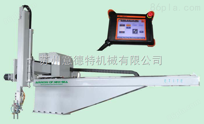
Industrial three-axis robotic arm
NegotiableUpdate on 01/12
- Model
- Nature of the Manufacturer
- Producers
- Product Category
- Place of Origin
Overview
The industrial three-axis robotic arm is used for various types of plastic injection molding machines with a capacity of 400-4000 tons, and is driven by a 3-axis AC servo. The finished arm is used to extract the product and the water outlet, and both the upper and lower arm structures are double jointed; The extraction time is 1.5 seconds, the full cycle time is 12 seconds, and the Z-load is 100kg (including finished products and fixtures). Applied to express delivery or various retrieval applications, especially for long shaped products such as car bumpers, door panels, decorative strips, etc.
Product Details
Industrial three-axis robotic armInstallation precautions:
1. The installation direction of the robotic arms on two adjacent injection molding machines should be clear.
2. All actions and movements do not hinder the opening and closing of the safety door of the injection molding machine.
3. All straight lines, rotations, and other actions of the robotic arm can be set on site and can be set within a certain error range. Once the error exceeds the set value, it will promptly alarm and stop the action, and display its fault information on the touch screen.
4. When the injection molding machine or robotic arm malfunctions, the injection molding machine and robotic arm will interlock. When the robotic arm malfunctions, the injection molding machine will stop operating; When the injection molding machine malfunctions, the robotic arm will also stop moving.
5. The arm has collision prevention function: when there is a misoperation, the program has an automatic collision prevention function, which can automatically judge and stop the action based on the motor torque, reducing the loss to a smaller extent.
6. The actions of the robotic arm and injection molding machine are consistent, which means there will be no collision or interference with the action of the injection molding machine, and the production cycle of the injection molding machine will not be excessively prolonged due to the action of the robotic arm.
7. When the injection molding machine stops (due to malfunction, normal shutdown, mold replacement, equipment maintenance, etc.), the mechanical arm can be manually placed in a safe position or other necessary position; It will not hinder the replacement of molds and equipment maintenance operations.
8. When the robotic arm malfunctions (such as not being in place, product not being removed, product falling, etc.), it will immediately sound an alarm and stop the machine. The fault will be displayed on the touch screen for quick troubleshooting. Key points of injection molding robotic arms in production design
9. Some products require a manipulator to include a release agent spray system. Release agent can be accurately sprayed into the mold cavity after mold opening (nozzle angle can be adjusted), and the dosage can be adjusted, and the spraying frequency can be set.
10. All parameters and data settings can be set and modified through a computer, and then downloaded to the robotic arm system for execution, or parameters and data can be directly set on the robotic arm.
Industrial three-axis robotic armMaintenance:
1. Guide rails and bearings
We should adhere to the cleaning of guide rails and bearings at all axes, as well as outstanding smoothness function. If the robotic arm operates in a dusty environment, it is necessary to regularly organize the guide rails. If you find any metal fragments or powder, it may indicate poor smoothness. In order to ensure a suitable smoothness, having an appropriate linear guidance system is crucial. Most robotic arms have an active smooth system and components that require periodic replacement.
2. Mechanical arm cycle
One of the key factors in maintaining the excellent operation of injection molding machine manipulators is to conduct brief investigations and listen attentively, which can reveal a lot of information about the overall operation of the manipulator. The robotic arm undergoes detailed motion operations and therefore listens for any abnormal sounds, such as whistling, clicking, etc., which indicate that the bearing cannot rotate normally or that some other component is stuck. The connection of the robotic arm moves along the guide rail equipped with power cables and vacuum hoses, and it will make a normal ticking sound, but this sound is smooth and stable. Check any bearings that can be investigated to ensure they rotate smoothly. Just by observing and listening to some signs of wear or adjustment needs, it can greatly help maintain the high-quality operation of the robotic arm.
3. Drive system
If the robotic arm is driven by a mounting bracket transmission gear, pay attention to whether there is any hesitation or shaking during operation. All movements, except for smooth and steady movements, can indicate damage to the drive system or the presence of some foreign objects inside. The injection molding robot arm is not as good as the stamping robot arm. When pushing downwards, the method to quickly check the movement or backlash between the installation beam and the transmission gear is to push and drag the motion arm to feel the abnormal movement (the back and forth movement is different). However, due to the high precision of normal manufacturer services, this experimental method will be very inaccurate. If you have doubts about the installation of beams and transmission gears, a better approach is to use a magnetic gauge holder with a long range. After adjusting the backlash according to the manufacturer's instructions, check the entire travel of the shaft to ensure that there is no tight fit between the installation beam and the transmission gear. If the backlash cannot be adjusted, the mounting bracket and transmission gear may show wear and require replacement. If it is necessary to repair the installation bracket and transmission gear, replace both components together and ensure long-term functionality. As for the shaft driven by the conveyor belt, pay close attention to the debris falling from the wear and tear of the conveyor belt and the harm to oneself. Carefully inspect the pulley and observe any signs of dust from the conveyor belt. Ensure that the conveyor belt, drive pulley, and pulley are arranged in a row. A conveyor belt that deviates from the direction will wear out very quickly. As long as it is a conveyor belt driven system, the pre load of the conveyor belt itself can be checked according to the manufacturer's instructions. These standards will inform you of the appropriate amount of error in the detailed orientation of the conveyor belt relative to the pulley.
4. Pneumatic system
Including multi axis servo drive, almost all robotic arms will have pneumatic function as long as there is wrist rotation and vacuum grasping action. Pay close attention to the suction cup of the filter regulator unit, as any accumulation of water indicates that the compressed air source passing through the system has excessive humidity. The presence of a small amount of water vapor may be transmitted to the pneumatic valve and actuator, causing oxidation and internal pollution, ultimately leading to sticking or intermittent sticking or failure of the regulator or actuator. If the suction cup is equipped with an active dehumidification system, contamination or discoloration on the suction cup also indicates an increase in moisture before removal. If water gathers in the suction cup, even if the time is short, it can still enter the system, posing the above question. If you notice any tangible damage to the pneumatic hose, there may be a leak in the system. If the air pressure circuit is filled with air at normal operating pressure and there is a leak somewhere in the circuit, you should be more likely to notice significant hissing sounds, which will help you determine the direction of the leak.