-
E-mail
ahhlby@126.com
-
Phone
17756952696
-
Address
Ruomao Road, Jingxian High tech Development Zone, Anhui Province
Product Categories
Anhui Huali Pump Industry Co., Ltd
IHFG Fluoroplastic lined Fluorine Pump
NegotiableUpdate on 08/18
- Model
- Nature of the Manufacturer
- Producers
- Product Category
- Place of Origin
Overview
IHFG Fluoroplastic lined Fluorine Pump
Product Details
1、 Introduction to IHFG Fluoroplastic lined Fluorine Pump
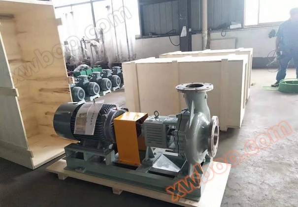
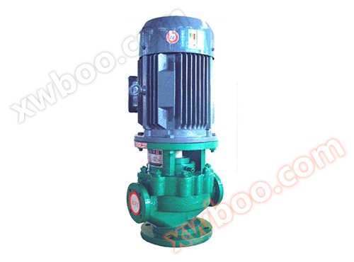
The IHF corrosion-resistant fluoroplastic centrifugal pump body adopts a metal shell lined with F46 (or imported PFA high-temperature fluoroplastic), and the pump cover, impeller, and shaft sleeve are all made of metal inserts wrapped in fluoroplastic and sintered as a whole. The shaft seal adopts an advanced external corrugated pipe mechanical seal, and the inlet and outlet are reinforced with cast steel bodies to enhance the pressure resistance of the pump.
This pump has the advantages of corrosion resistance, wear resistance, high temperature resistance, anti-aging, high mechanical strength, smooth operation, advanced and reasonable structure, strict and reliable sealing performance, easy disassembly and maintenance, and long service life.

2、 IHFG Fluoroplastic lined Fluorine Pump Parameters

3、 Characteristics of IHFG Fluoroplastic lined Fluorine Pump
The prominent feature of fluoroplastic self-priming pump is its self-priming function, which can pump liquids below the installation position of the pump, with stable performance and simple operation. It only needs to be filled with liquid before the first use of the pump, and after the second and subsequent uses, there is no need to fill with liquid, and the pump can be turned on directly.
The self-priming height can be determined within 2 to 4 meters based on the density of the medium, and the submersible sewage pump is a better choice to replace bulky submersible pumps.
4、 IHFG Fluoroplastic lined Fluorine Pump Structure
1. Fluoroplastic lined pump body, also known as pump casing: It is made of outer steel lined with fluoroplastic, and the parts in contact with the flowing liquid are made of fluoroplastic, which can effectively resist corrosion. It is also the main body of the water pump, which plays a supporting and fixing role and is connected to the bracket for installing bearings.
2. The impeller is the core part of a centrifugal pump, made of fluoroplasticfluorine-linedThe pump impeller is made of perfluorinated material with a metal structure inside, which not only has a good anti-corrosion effect, but also has high speed and output. The blades on the impeller play a major role, and the impeller needs to pass a static balance test before assembly. The inner and outer surfaces of the fluoroplastic impeller are smooth to reduce frictional losses caused by water flow.
3. Fluoroplasticfluorine-linedThe function of the pump shaft is to connect the pump shaft and the electric motor, transmitting the torque of the electric motor to the impeller, so it is the main component for transmitting mechanical energy.
4. Fluoroplasticfluorine-linedPump seal, also known as leak reducing ring. Excessive clearance between the impeller inlet and the pump casing can cause water in the high-pressure area of the pump to flow through this clearance to the low-pressure area, affecting the pump's water output and reducing efficiency. Insufficient clearance can cause friction and wear between the impeller and the pump casing.
In order to increase reflux resistance, reduce internal leakage, and prolong the service life of the impeller and pump casing, a sealing ring is installed at the junction of the inner edge of the pump casing and the outer edge of the impeller, with a sealing gap maintained between 0.25 and 1.10mm. fluoroplasticfluorine-linedThere are single-sided mechanical seals and containerized double end mechanical seals for pump seals.
6. Bracket: The bracket is a component that connects the pump body and the motor, mainly playing a role in connection, support, and balance.
6. Motor: Connected to the pump shaft in an empty shaft form for stable operation, made of fluoroplasticfluorine-linedThe pump adopts a 380V three-phase motor.

5、 Installation of IHFG fluoroplastic lined fluorine pump
1. During installation, the weight of the pipeline should not be added to the water pump, and there should be separate supporting bodies to avoid deformation that affects operational performance and lifespan.
2. The pump and motor are integrated structures, so there is no need to align them during installation, making it very convenient.
3. During installation, the anchor bolts must be tightened to avoid the impact of vibration on pump performance during start-up.
4. Before installing the water pump, carefully inspect the pump passage for any hard objects (such as stones, iron particles, etc.) that may affect the operation of the pump, in order to prevent damage to the impeller and pump body during operation.
5. For the convenience of maintenance and safety of use, a regulating valve is installed on each inlet and outlet pipeline of the pump, and a pressure gauge is installed near the pump outlet to ensure that it operates within the rated head and flow range, ensuring the normal operation of the pump and increasing its service life.
6. Pumps used in suction applications should be equipped with bottom valves, and the inlet pipeline should not have too many bends, and there should be no water or air leakage.
7. The discharge pipeline, such as a check valve, should be installed outside the gate valve.
8. After installation, if the pump shaft is moved, there should be friction sound or jamming phenomenon of the impeller. Otherwise, the pump should be disassembled to check the cause.
9. The installation methods of pumps are divided into rigid connection and flexible connection installation.