-
E-mail
2885348797@qq.com
-
Phone
18202180327
-
Address
No. 253 Yulu Road, Jiading District, Shanghai
Product Categories
Ankerui E-commerce (Shanghai) Co., Ltd
Wholesale of End of Line Intelligent Monitoring Modules
NegotiableUpdate on 02/08
- Model
- Nature of the Manufacturer
- Producers
- Product Category
- Place of Origin
Overview
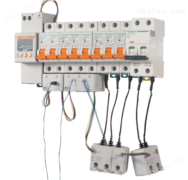
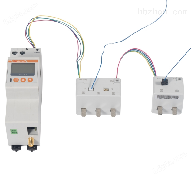
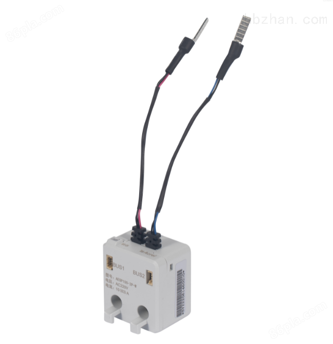
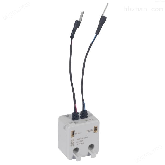
The AESP110-2P terminal intelligent monitoring module is used for electrical safety monitoring in low-voltage terminal distribution networks in industrial, commercial, civil buildings, infrastructure and other fields of indoor buildings and similar places. This module is used in conjunction with circuit breakers to monitor key electrical factors of power lines, such as voltage, current, power, temperature, energy consumption, etc., in real time. It has functions such as early warning and alarm, energy metering and statistics. This series of products is suitable for low-voltage power grid systems with single-phase, dual live, three-phase three wire, and three-phase four wire neutral point direct grounding (TT).
Product Details
1. Overview
The AESP110 series terminal intelligent monitoring module (hereinafter referred to as the module) is applied to industrial, commercial, and civil buildings in indoor buildings and similar placesLow voltage terminal distribution network in the fields of construction and infrastructure. This module is used in conjunction with a circuit breaker to address key electrical factors of the power line, such as voltage and electricityReal time monitoring of flow, power, temperature, energy consumption, etc., with functions such as early warning and alarm, electricity metering and statistics.This series of products is suitable for single-phase, dual live, three-phase three wire, three-phase four wire neutral point direct grounding(The low voltage power grid system of TT.
AESP110-2P terminal intelligent monitoring module for electrical safety monitoring
AESP110-2P terminal intelligent monitoring module for electrical safety monitoring
2. Product model
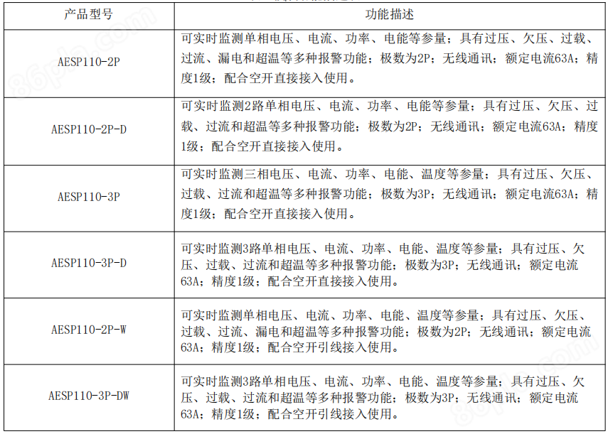
AESP110 series terminal intelligent monitoring module
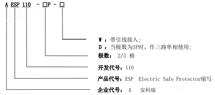
Table 1 Module Function Description Table

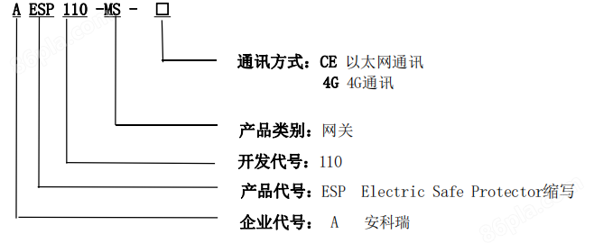
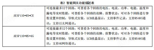
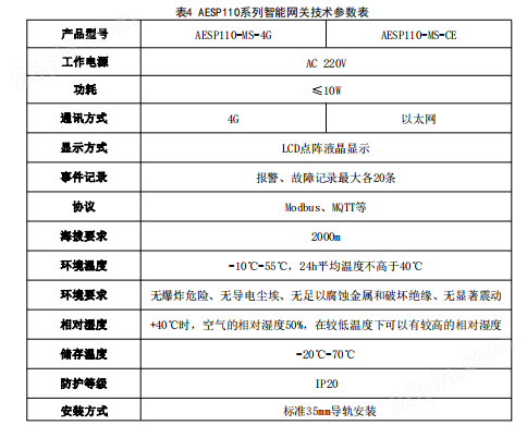
Smart Gateway
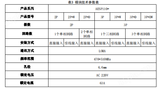
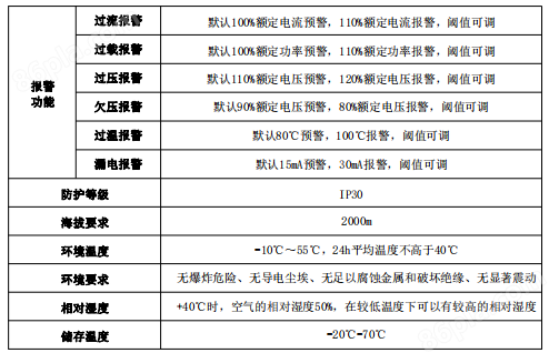
3. Technical Specifications
4. Installation and Wiring
4.1. Appearance and installation dimensions (unit: mm)
2P
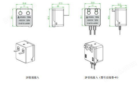
3P
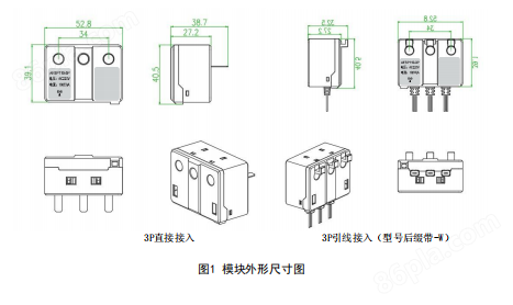
Smart Gateway
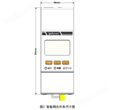
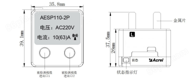
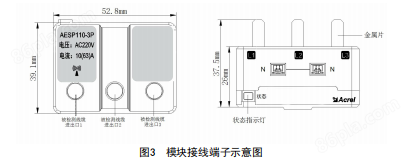
4.2. Instructions for wiring terminals
AESP110-2P terminal block
AESP110-3P wiring terminal
Intelligent gateway wiring terminal
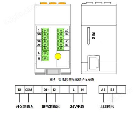
4.3. Wiring diagram
Module wiring diagram
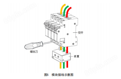
4.4. Installation methodFigure 6 shows an example of the installation and wiring of AESP110 series online monitoring modules in conjunction with circuit breakers and intelligent gateways, for reference only.
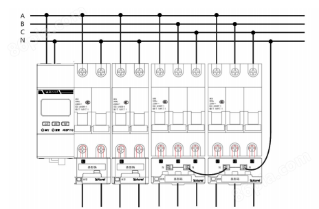
Figure 6 Example diagram of module installation and wiring
Note: Various types of modules can be installed in any combination, and a gateway can connect up to 16 monitoring modules for each circuit.
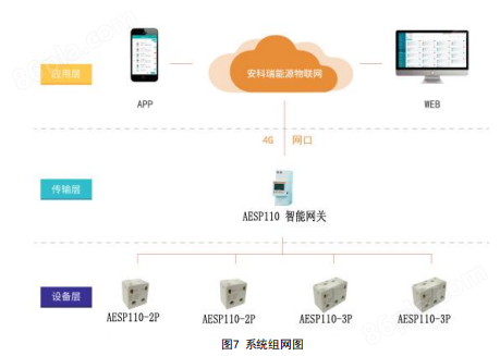
4.5. System networking diagram
Figure 7 shows the network diagram of the AESP110 series monitoring module in conjunction with the intelligent gateway system
Similar Product Recommend
