-
E-mail
ocetest@126.com
-
Phone
15820775741
-
Address
208, Building E, Yuetong Comprehensive Building, Meilong Road, Longhua New District, Shenzhen
Product Categories
Shenzhen Guoce Electronics Co., Ltd
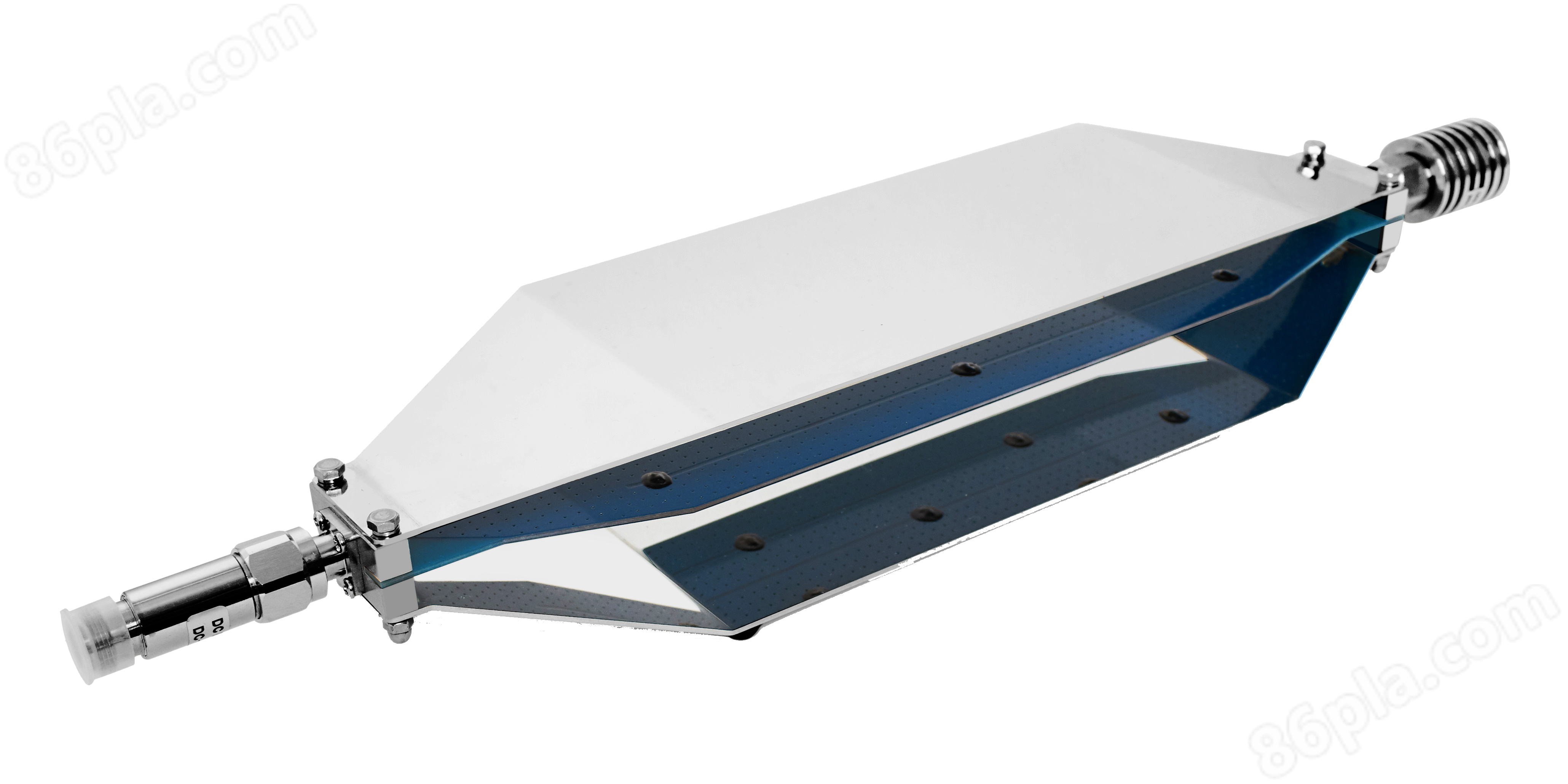
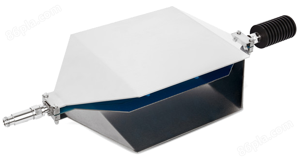
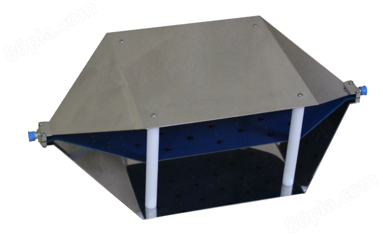
Which is good for selling TEM cells
NegotiableUpdate on 01/17
- Model
- Nature of the Manufacturer
- Producers
- Product Category
- Place of Origin
Overview
The open TEM transverse wave cell TBTC EMC electromagnetic compatibility radiation interference test or immunity test is usually conducted in an electromagnetic shielding room, using an antenna to receive radiation signals. Due to bandwidth limitations, multiple antennas are required to cover the entire frequency range. In addition, shielded darkrooms require a large space and equipment costs for standard consistency testing are high. Engineers in small and medium-sized enterprises often have to rely on work experience and practical methods to design products that comply with EMC. However, it is estimated that over 50% of the products did not pass the test. When a new product is sent to a certification laboratory for compliance testing, the cost of testing failure is very high. Not only is the cost of retesting high, but project progress and market promotion are also delayed. Therefore, what is needed is a reasonably priced laboratory where engineers can conduct radiation interference pre testing in the laboratory before compliance testing. The TEM unit is a device used for desktop radiation interference testing. The open TEM unit developed by Tekbox covers a frequency range of up to 2GHz and is available even at higher frequencies (6GHz).
Product Details
Open TEM transverse wave cell TBTC
Overview
EMCElectromagnetic CompatibilityRadiation disturbance testing or immunity testing is usually conducted in electromagnetic shielding rooms, using antennas to receive radiated signals. Due to bandwidth limitations, multiple antennas are required to cover the entire frequency range. In addition, shielded darkrooms require a large space and the equipment cost for standard consistency testing is high.
Engineers in small and medium-sized enterprises often have to rely on work experience and practical methods to design products that comply with EMC. However, it is estimated that over 50% of the products did not pass the test. When a new product is sent to a certification laboratory for compliance testing, the cost of testing failure is very high. Not only is the cost of retesting high, but project progress and market promotion are also delayed.
Therefore, what is needed is a reasonably priced laboratory where engineers can conduct radiation interference pre testing in the laboratory before compliance testing. The TEM unit is a device used for desktop radiation interference testing. The open TEM unit developed by Tekbox covers a frequency range of up to 2GHz and is available even at higher frequencies (6GHz).
The TEM unit can be used in conjunction with a spectrum analyzer to perform verification testing on products before and after EMC related design modifications. The TEM Cell device cannot obtain the same measurement results as certified laboratory measurements, but it can effectively indicate whether the product design has radiation interference. Engineers will clearly see the radiation situation, whether the product changes have improved EMC performance, or whether it remains unchanged. The use of TEM units eliminates speculation about product radiation interference.
TEMUnit is a strip line device used for radiation emission and immunity testing of electronic devices. Due to its size and cost, it is not a substitute for certification testing laboratories, but a convenient alternative method for measuring in laboratories.
TEMThe unit consists of partitions, conductive strips in the middle, and grounded walls. Presented as a 50 Ω strip line with geometric design. The device under test (DUT) is placed between the bottom wall and the partition.
TBTC1 / 2/3It is an open TEM unit without sidewalls, making it easy to place the DUT. The absence of sidewalls may pick up environmental background noise, but it can be taken into account by measuring the unit output signal for environmental noise before powering on the DUT.
TEM CellUsed for EMC consistency pre-test - radiation immunity
The anti-interference test is conducted by connecting the output of the RF signal generator to the TEM unit after passing through the RF amplifier. The partition radiates the RF signal into the DUT, which is usually amplitude modulated (AM) or pulse modulated
Compared with standard TEM units of the same size, Tekbox open TEM units have better frequency response. The available bandwidth is limited by the high-order wave modes of TEM units. The design of Tekbox TEM unit achieves resistance perpendicular to the desired wave propagation direction. Therefore, higher-order waves and resonances are suppressed.
All TEM units are equipped with 50 Ω/25W RF terminal loads and DC blocks to protect the input of spectrum analyzers or receivers
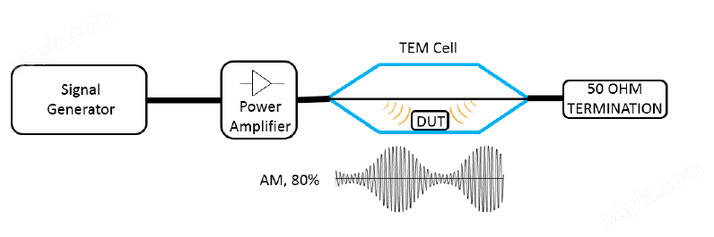
Complete anti-interference solution
Spectrum analyzer: can use PuYuan DSA815, DingYang SSA3021X, VSA6G2A or other brands, or can use a second-hand spectrum analyzer (such as N9020A)
RF power amplifier: Tekbox offers a range of modulated power amplifiers that are perfect for low-cost immunity testing. For example: TBMDA1 (40M-3G), TBHDR1 (30K-1.5G), etc. These amplifiers have built-in modulators to generate the desired modulation format, driven by the tracking source output of the spectrum analyzer, so there is no need to invest in an RF signal generator
According to the selected modulation signal amplifier and TEM unit, this setting can generate field strengths of up to several hundred volts. For more information, please refer to
Test the data sheet of the modulation amplifier.
Considering that the electric field is orthogonal to the partition, in order to consider the worst-case scenario of DUT testing, please position it inside the TEM unit so that the PCB trace is perpendicular to the partition
Board direction, expose it to the field strength
TBTC0Apply RF power |
Field strength between partition and wall |
10W(40dBm) |
799 V/m |
1W(30dBm) |
253 V/m |
0.1W(20dBm) |
82 V/m |
0.01W(10dBm) |
25 V/m |
TBTC0 ,Field strength and RF power
TBTC1Apply RF power |
Field strength between partition and wall |
10W(40dBm) |
447 V/m |
1W(30dBm) |
141 V/m |
0.1W(20dBm) |
44 V/m |
0.01W(10dBm) |
14 V/m |
TBTC1 ,Field strength and RF power
TBTC2Apply RF power |
Field strength between partition and wall |
10W(40dBm) |
224 V/m |
1W(30dBm) |
71 V/m |
0.1W(20dBm) |
22 V/m |
0.01W(10dBm) |
7 V/m |
TBTC2 ,Field strength and RF power
TBTC3Apply RF power |
Field strength between partition and wall |
10W(40dBm) |
148 V/m |
1W(30dBm) |
47 V/m |
0.1W(20dBm) |
14 V/m |
0.01W(10dBm) |
5 V/m |
TBTC3 ,Field strength and RF power
TEM CellUsed for EMC consistency pre-test - radiation disturbance
TEMWhen used in conjunction with a spectrum analyzer or receiver, the unit can test and verify the product before and after EMC related rectification, and engineers can clearly see the rectification effect
technical indicators
TBTC0 | |
length |
390 mm |
width |
100 mm |
height |
62 mm |
Height of spacer |
28 mm |
Dimensions of the rectangular area below the spacer |
19×7×2.8 cm |
connector |
NType - Mother |
unit impedance |
50Europe |
impedance |
377Europe |
RF input power |
10W(Limited by providing 50 terminal connections) |
input return loss |
S11 @ 3.15G< -1.5dB |
transmission loss |
3G< 3dB, 6G < 4dB |
TBTC1 | |
length |
390 mm |
width |
200 mm |
height |
108 mm |
Height of spacer |
50 mm |
Dimensions of the rectangular area below the spacer |
19×13×5 cm |
connector |
NType - Mother |
unit impedance |
50Europe |
impedance |
377Europe |
RF input power |
25W(Limited by providing 50 terminal connections) |
input return loss |
S11 @ 1.2G<-20dB; 2.1G<-17dB; 3G<-14dB |
transmission loss |
1.4G<1dB, 2.1G<3dB,3G<6dB |
TBTC2 | |
length |
636 mm |
width |
300 mm |
height |
205 mm |
Height of spacer |
100 mm |
Dimensions of the rectangular area below the spacer |
23×28×10 cm |
connector |
NType - Mother |
unit impedance |
50Europe |
impedance |
377Europe |
RF input power |
25W(Limited by providing 50 terminal connections) |
input return loss |
S11 @ 800MHz<-15dB; 1.5G<-10dB; 3G<-8dB |
transmission loss |
800MHz<1dB, 1.15G<3dB |
TBTC3 | |
length |
1038 mm |
width |
501 mm |
height |
305 mm |
Height of spacer |
150 mm |
Dimensions of the rectangular area below the spacer |
36×48×15 cm |
connector |
NType - Mother |
unit impedance |
50Europe |
impedance |
377Europe |
RF input power |
25W(Limited by providing 50 terminal connections) |
input return loss |
S11 @ 700MHz<-16dB; |
transmission loss |
730MHz<3dB |
DC-Block 50V-6GHz-N | |
connector |
N-Male / Female |
Nominal impedance |
50Europe |
Continuous RF power |
2W |
Continuous RF voltage |
50V RMS |
frequency |
500KHz – 6GHz |
VSWR |
≤ 1.2 |
insertion loss |
MHz 0.3 0.7 1 10 100 1000 3000 |
dB 7.5 3 1.5 0.02 0.02 0.06 0.2 | |
RFTerminal 50 Ω -3GHz-25W-N | |
connector |
N |
Nominal impedance |
50Europe |
Continuous RF power |
25W |
frequency |
DC-3GHz |
VSWR |
≤1.2 |
Third-order intermodulation |
≤120dBc |
RFTerminal 50 Ω -6GHz-10W-N | |
connector |
N |
Nominal impedance |
50Europe |
Continuous RF power |
10W |
frequency |
DC-6GHz |
VSWR |
≤1.2 |
Third-order intermodulation |
≤120dBc |
warranty | |
warranty |
1year |
Similar Product Recommend