-
E-mail
410926377@qq.com
-
Phone
15613793280
-
Address
Cangzhou West Industrial Zone, Hebei Province
Product Categories
Cangzhou Ranbo Instrument Equipment Co., Ltd
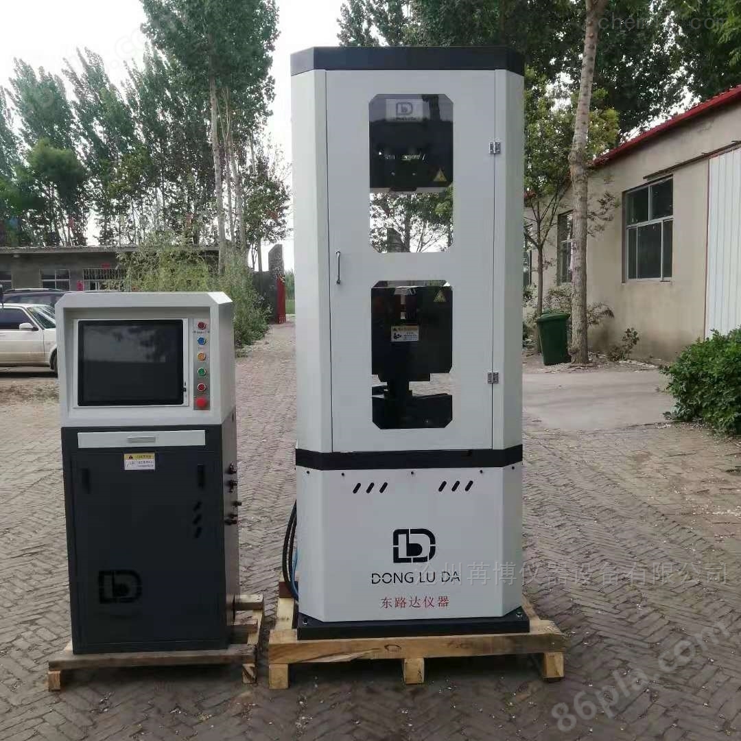
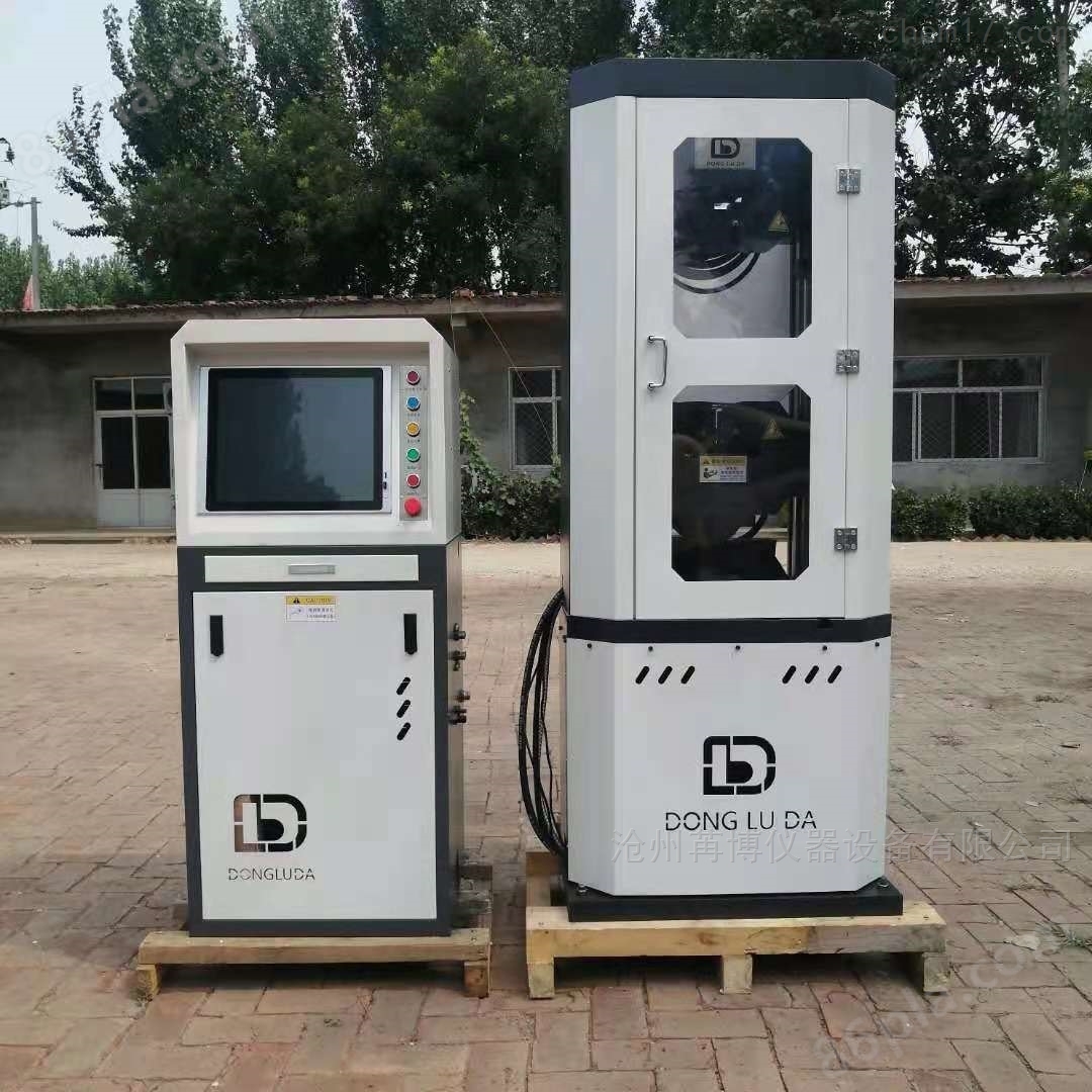
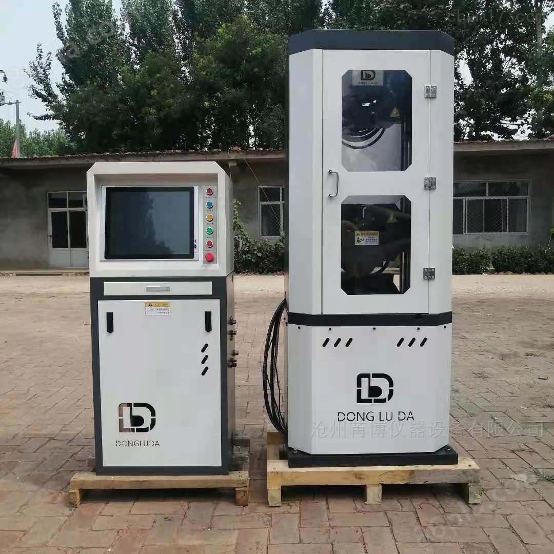
Which is a good 100 ton electro-hydraulic servo material testing machine
NegotiableUpdate on 01/17
- Model
- Nature of the Manufacturer
- Producers
- Product Category
- Place of Origin
Overview
30 ton/60 ton/100 ton electro-hydraulic servo material testing machine WES-B series microcomputer controlled testing machine adopts the design of microcomputer controlled electro-hydraulic servo valve loading and separate main body and control cabinet. It has the characteristics of easy operation, stable and reliable work, high testing accuracy, and smooth force application. It is suitable for tensile, compressive, bending, and shear tests of materials such as metal, cement, concrete, and plastic.
Product Details
30 ton/60 ton/100 ton electro-hydraulic servo material testing machinethe structure of
The main body of this equipment consists of a height adjustable support frame (composed of a machine base, screw rod, and moving crossbeam (lower jaw seat)) and a working frame (composed of a working oil cylinder, piston, table, bracket, and upper crossbeam (upper jaw seat)). Its working principle is: the high-pressure oil pump supplies oil to the working cylinder, and through the movement of the piston, the worktable and upper crossbeam (upper jaw seat) are pushed upward to perform tensile or compression tests on the sample. The tensile test is conducted between the upper crossbeam and the moving crossbeam of the host, and the compression test is conducted between the platform of the host and the moving crossbeam. The adjustment of the experimental space is achieved by driving the double screw synchronous rotation through the driving mechanism (lifting motor, sprocket, chain, etc.) to lift the moving crossbeam.
Electrical principle
This equipment adopts three-phase 380V, two-phase 220V 50Hz AC power supply. The main circuit includes the oil pump motor and the lifting motor. Fuses are connected to the main circuit and the control circuit respectively to prevent excessive current. A thermal relay is also connected in series before the oil pump motor and the lifting motor to prevent motor overload.
3. Installation
unboxing acceptance
After you open the box, please check the quantity of equipment and accessories according to the order contract and packing list to ensure completeness. If any shortage or damage is found, please notify our company as soon as possible for timely handling.
Pre-installation preparation
The testing machine should be installed in a clean, dry, vibration free room with a room temperature of 10 ℃ -35 ℃. Sufficient space (≥ 0.7m) should be left around the testing machine for testing and maintenance purposes.
The main body and control cabinet of the testing machine should be installed on a concrete foundation. The basic dimensions shall be based on the shape and foundation drawings, leaving room for anchor screws and other devices such as electrical wires and pipelines. The upper plane of the foundation shall be horizontally aligned.
Preliminary calibration of installation accuracy
Preliminary calibration of the main body: Use a frame level or borrow a plumb bob from the attachment to calibrate the verticality of the column in two perpendicular directions, and adjust it by inserting a small iron piece at the bottom of the main body. Hang the anchor screws securely.
Use cement mortar to solidify the screws at each foot, and fill the gaps between the testing machine and the ground. Maintain for one week.
Connection of hydraulic system
a. Remove all binding materials and clean the inside of the oil pipe with clean kerosene.
b. Check if the gasket at the joint is intact. If it is damaged due to transportation, it should be replaced with a new gasket that comes with the machine to prevent oil leakage under high pressure.
c. Use a suitable wrench to connect each oil pipe.
d. This equipment usually uses N68 anti-wear hydraulic oil. When the ambient temperature is too high, N100 hydraulic oil can be added as needed to increase viscosity.
Electrical installation
The power supply voltage of this equipment is three-phase 380V and two-phase 220V, and the equipment must be grounded. The electrical connection between the main body and the control cabinet is made using plugs. Before powering on, the iron door of the control cabinet should be opened to check for any loose connections, loose fuses, and to remove dust and debris from the electrical box. After confirming that the device is connected to the power supply line, press the "Power" button on the control panel to check if the lifting action of the clamp seat matches the text on the button. If it is opposite, switch the positions of any two phase wires.
debug
3.6.1 Start the oil pump and repeatedly lift the piston to exhaust the air in the oil cylinder and oil pipe. It can be observed that the return oil is continuous and stable.
If the pointer is found to be stagnant in a certain interval during the pressure test, the following operations should be performed:
a. Adjust the work pressure to half of the range and stabilize it.
b. Open the iron door of the control cabinet, unscrew the exhaust plug on the right side of the outer circle of the pressure reducing valve, exhaust the air, and then turn it back.
*c. When performing the above operations, attention must be paid to: ① The work pressure should not be too high; ② When turning the exhaust plug, use gentle force to prevent it from twisting and breaking.
test drive
a. Pull the cold-formed support evenly apart on both sides, ensuring that it does not touch when moving the crossbeam up and down;
b. Install a spherical lower pressure plate on the platform, and move the crossbeam up and down to make the distance between the upper and lower pressure plates about 20mm;
c. Start the oil pump, activate the software control system to raise the table, and slowly increase the pressure to 80% of the range;
d. Check for oil leakage at each oil pipe joint;
e. If there is oil leakage, tighten the joint after unloading the force.
Similar Product Recommend