-
E-mail
13901452326@139.com
-
Phone
17798959858
-
Address
Chuangye Road, Baoying Liubao Industrial Concentration Zone, Yangzhou City, Jiangsu Province
Product Categories
Yangzhou Zhongyue Electric Co., Ltd
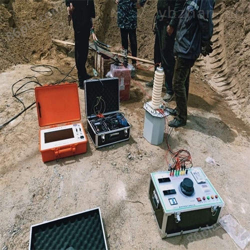
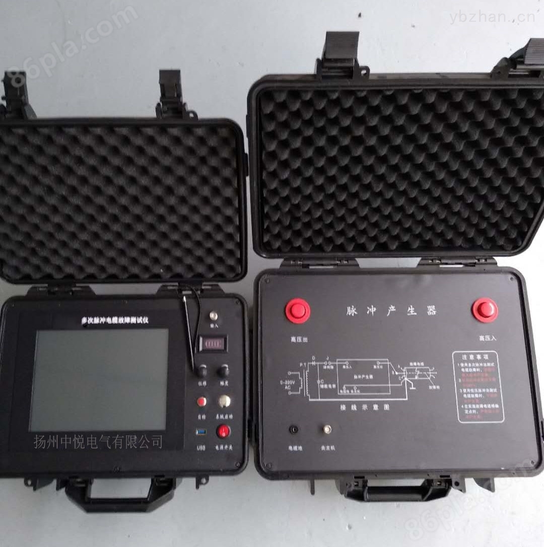
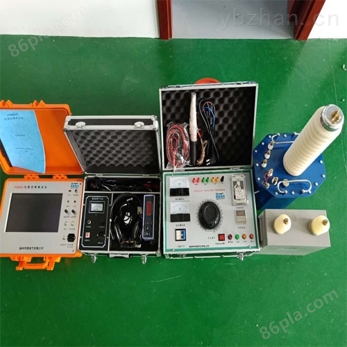
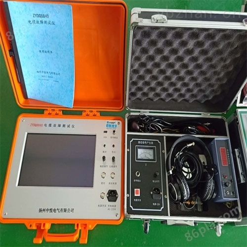
The direct flash current method direct buried cable fault tester is simple and easy to use
NegotiableUpdate on 01/17
- Model
- Nature of the Manufacturer
- Producers
- Product Category
- Place of Origin
Overview
The direct buried cable fault tester has multiple functions such as low-voltage pulse distance measurement, pulse current distance measurement, acoustic magnetic synchronous fixed-point detection, and path detection. Compared with traditional split devices, its equipment quantity, volume, and weight are greatly reduced, and it is powerful, easy to use, compact, and portable. It is a replacement product for traditional devices.
Product Details
Direct buried cable fault tester
Product Features
1. Adopting an industrial control embedded computer platform system and an industrial grade usage environment to achieve * stability. Lithium battery power supply, convenient for on-site testing.
2. Domestically, a 12.1-inch large screen touch system is adopted with integrated software for the entire computer operating platform, bidding farewell to the era of cable instrument microcontrollers, and equipped with cable fault testing software and cable data management software.
3. Adopting a new USB communication interface, stable signal acquisition is achieved. Paired with a laptop, dual control and dual display can be achieved. The host can automatically select a low 25MHz sampling frequency to meet the testing requirements of cables of different lengths, reducing rough measurement errors.
4. The software implements automatic fault search, distance display, and dual cursor movement with an accuracy of 0.1 meters. The waveform can be compressed and expanded arbitrarily, and two waveforms closer to the standard are randomly displayed on the same screen for accurate comparison and analysis, improving testing accuracy and reducing errors.
5. Supporting newly opened 3G communication terminals, providing users with timely and accurate waveform analysis and communication guidance for on-site testing, ensuring worry free work.
6. The 4G electronic disk memory has multiple types of on-site waveforms and physical wiring diagrams, which can be easily used with just a click. The cable data management software can provide comprehensive cable file management, providing reference and assistance for cable maintenance work and precise positioning.
7. The key precise fixed-point instrument part, which directly displays the distance between the tester and the fault point digitally, is another innovation of similar fixed-point technology in China, providing strong support for quickly and accurately finding cable faults and reducing power outage losses.
8. The intelligent combination sampler replaces tedious on-site wiring, has the characteristics of intuitive waveform, easy analysis, isolation from high voltage, and safety for the host and operators.
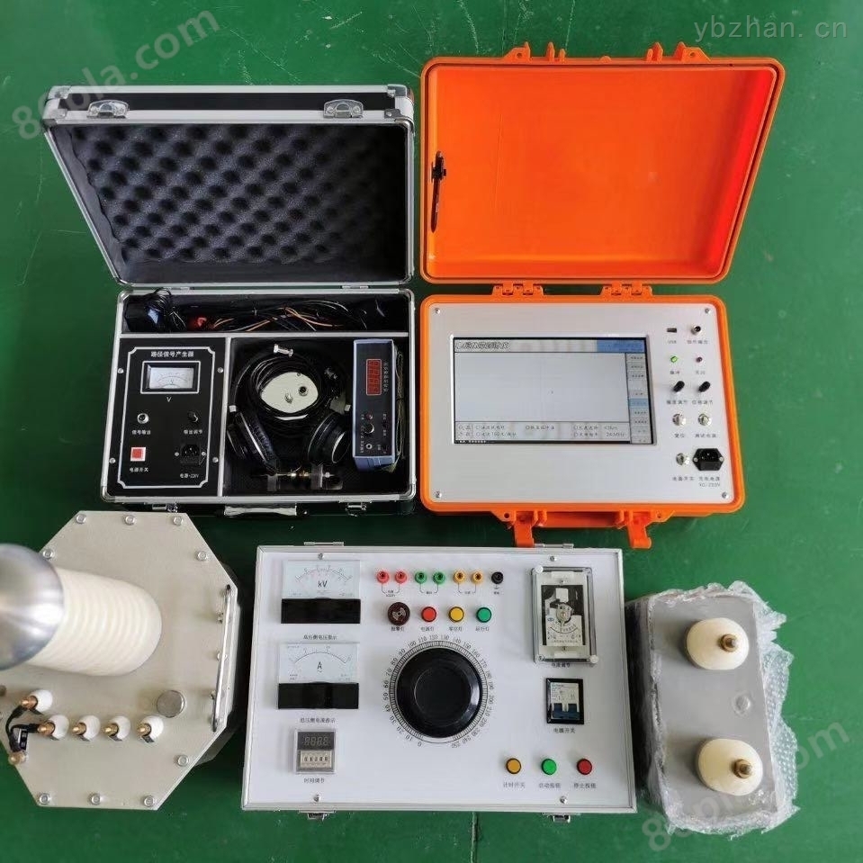
9. There are three types of high-voltage discharge parts available for users to choose from, with a high-frequency high-voltage power supply of 8.9kg replacing the 65kg test transformer and operation box,.
Technical Indicators:
▲Testing methods: Low voltage pulse method, impulse lightning current method, direct lightning current method
▲test distanceNot less than 40km
▲Accuracy: within 2Km, not exceeding 1 meter; Above 2Km and not exceeding 3 meters
▲Z short test distance (blind spot):5-10 meters
▲Accurate positioning error: ± 0.2m
▲ Test error: System error less than ± 1%
▲Instrument sampling frequency: 6.25MHz, 10MHz, 25MHz, 50MHz, 100MHz, (adaptive pulse width)
▲Power supply and power consumption: AC 220V ± 10%, not exceeding 15W
DC 12V (7AH) not exceeding 20W
▲Standby time: can be used continuously for about 4 hours
▲Signal frequency: 15KHz sine wave
▲Output power: Pomax ≥ 100W
▲Environmental temperature: -10 ℃ to+40 ℃
▲Dimensions: 180mm × 300mm × 400mm
▲Relative humidity: RH ≤ 85% (25 ℃)
▲Host weight: 9.8kg
Notes:
1. Before conducting fault testing, carefully read the instrument manual, master the operating steps, and ensure safe wiring of the instrument.
One of the main features of this cable fault tester is that it can operate without an external power supply, and the equipment is entirely powered by the built-in battery. This brings great convenience to the use of the instrument and improves safety factors. The status of the internal power battery is displayed by the "undervoltage" indicator light on the instrument panel. When the voltage is insufficient, the "undervoltage" indicator light will flash to indicate. When the "undervoltage" indicator light flashes, the instrument can continue to work for more than half an hour. At this time, it is necessary to promptly connect the charging power source for charging. When testing cable faults on site, the battery voltage of the machine must be sufficient. When charging from an external power source, the "undervoltage" indicator light is on, indicating that charging is in progress. Generally, it takes four hours to charge. The charging indicator light on the power adapter changes from red to green, indicating that the battery is fully charged. After the battery voltage is sufficient, it can ensure normal operation for more than 2 hours. The instrument can be connected to an AC power source for float charging during use. However, during high-voltage flashover testing, it is necessary to disconnect from the external AC power supply.
3. Due to the instantaneous high voltage of thousands of volts generated by the connection between the cable ground wire and the high-voltage equipment during the operation of the instrument in the impulse flashover state (including the eighth pulse method), when grounding the "eighth pulse generator" of the instrument, the instrument ground wire must be separately connected to the system ground with a ground wire, and cannot be connected elsewhere. Otherwise, it may cause the instrument to crash or even damage the instrument when subjected to high pressure impact.
Under normal circumstances, there should be no issues with the onboard computer and data collector. If there is a problem, most of the time it is due to poor contact of the connecting cable between the industrial control computer board and the motherboard. The replacement method can be used to exclude the prompt information from the instrument.
Direct buried cable fault tester
Similar Product Recommend