-
E-mail
2881392112@qq.com
-
Phone
18761595061
-
Address
No. 5, ASEAN Road, Nanzha Street, Jiangyin City, Jiangsu Province
Product Categories
Jiangsu Ankerui Electric Appliance Manufacturing Co., Ltd
How much does the remote meter reading system for domestic industrial parks cost
NegotiableUpdate on 01/17
- Model
- Nature of the Manufacturer
- Producers
- Product Category
- Place of Origin
Overview
The remote meter reading and power monitoring system of Ankerui Industrial Park adopts on-site networking method. After networking, it communicates through fieldbus and transmits to the background remotely. Real time monitoring and management of substation electricity is achieved through the power management system.
Product Details
Ankrui Chen Cong
1Remote Meter Reading and Power Monitoring System for Ankerui Industrial ParkOverview
this systemAdopting intelligent power meters to collect various electrical parameters and switch signals at the distribution site. The system adopts on-site networking method, and after networking, it communicates through fieldbus and transmits to the background remotely. Real time monitoring and management of substation electricity is achieved through the power management system.
2. Demand analysis
Solution:
1) Integrated automation system for 10kV/35kV substation;
2) Intelligent monitoring backend system for distribution network switch station;
3) Coordination and control platform for electricity demand side.
To ensure the statistics and analysis of electricity load for production management and real-time monitoring of hazardous sources. Real time online monitoring of parameters such as voltage (U), current (I), and power (P) is required for the incoming and outgoing circuits in the distribution box at the project site. Once the monitored parameters at the monitoring point are abnormal, timely detection and alarm can be triggered, and relevant personnel can take necessary measures to avoid safety accidents. The automatic meter reading function saves manpower and material resources, and the power trend curve function can intuitively display the working status and time of each circuit, making it convenient for users to identify abnormal power consumption circuits and make timely corrections. It establishes a multi-level energy metering system to provide energy analysis basis.
The supplier's products should have high safety and reliability, be easy to expand, and be easy to repair and maintain. The products provided by the supplier should at least meet the technical requirements, but not limited to that, their technical performance should meet the requirements for monitoring distribution box data.
3 Remote Meter Reading and Power Monitoring System for Ankerui Industrial ParkSystem solutions
According to the actual situation of the project site, the overall network structure of the Acrel-2000 system adopts shielded twisted pair cables directly connected to the data collector and then directly connected to the monitoring host in the duty room through Ethernet cables, ensuring the stability and real-time transmission of the power management monitoring system.
1) Station control management team
The station control management is the direct window for human-machine interaction for the management personnel of the power monitoring system. In this project, it mainly refers to the monitoring host of the distribution room.
2) Network communication layer
The communication layer is mainly composed of collectors, Ethernet devices, and bus networks. The main function of the communication management machine is to monitor on-site intelligent instruments; The main function of Ethernet devices and bus networks is to achieve data exchange between substations and main stations, making the management of the distribution system centralized, informationized, and intelligent, greatly improving the safety, reliability, and stability of the distribution system, and achieving the goal of unmanned operation.
The project can use Ankerui's self-developed communication management machine ANet-2E8S1, which provides 2 10/100M Ethernet interfaces, 8 optocoupler isolated RS485 and 1 RS232 (debugging port), and can support 256 measuring devices.
ANet intelligent communication management machine provides rich protocol library support to achieve intelligent device interconnection among different secondary device suppliers.

3) On site equipment layer
The on-site equipment layer is the data acquisition terminal, mainly composed of microcomputer protection and intelligent instruments. The intelligent instruments are connected to the communication server through shielded twisted pair RS485 interface and MODBUS communication protocol bus connection. They are then connected to the monitoring host in the distribution room through the communication server for networking and remote control.
4 System Functions
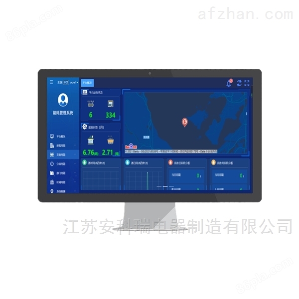
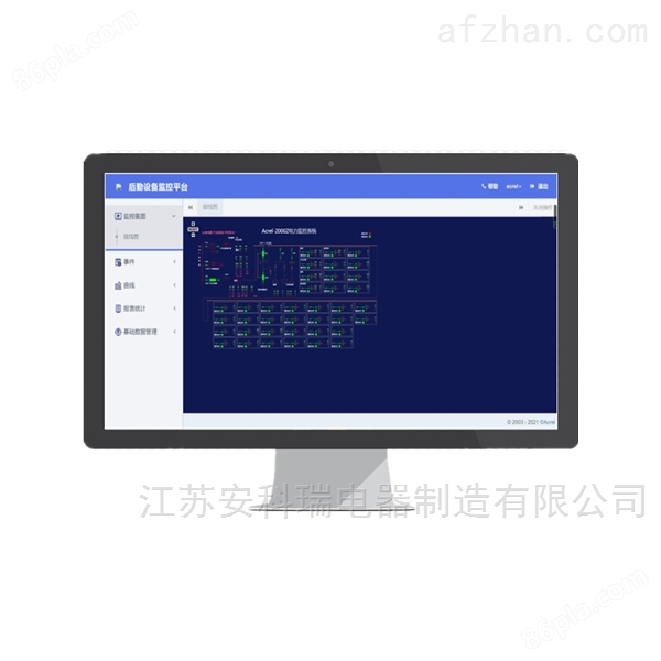
The real-time monitoring system diagram is the main monitoring screen, which mainly monitors the operation status of all circuits in the substation in real time.
The remote signaling and telemetry alarm function mainly completes the monitoring of the switch operation status and load incoming line of each low-voltage outgoing circuit, and pops up an alarm interface to indicate the specific alarm position and sound an alarm for switch displacement and load limit exceeding, reminding the duty personnel to handle it in a timely manner. Load exceeding the limit is within the corresponding permissions
You can freely set it below.
The event alarm recording function mainly completes the recording of alarm information events and their occurrence times during the query time period, providing a basis for duty personnel and analyzing the causes of accidents.
The parameter meter reading function is mainly used to query the electrical parameters of the low-voltage outgoing circuits. Support electronic parameter query at any time, with functions such as data export and report printing. This report queries the electrical parameters of various low-voltage circuits in and out of the project distribution box, mainly including three-phase current, active power, and active energy. The names of each circuit in this report are associated with the database, making it convenient for users to modify the circuit names.
The electricity consumption report function allows users to select a time period for querying, supports cumulative electricity consumption queries at any time period, and has functions such as data export and report printing. Provided reliable electricity reports for the on duty personnel. The names of each circuit in this report are associated with the database, making it convenient for users to modify the circuit names. As shown in the figure below, users can directly print the report and save it in Excel format to another location.
Similar Product Recommend