-
E-mail
13852628788@163.com
-
Phone
13852628788
-
Address
No. 88-1, Xinqiao Industrial Park, Jingjiang City
Product Categories
Jiangsu Jinxin Pump Industry Co., Ltd

WFB type high-pressure high-power unsealed self-priming pump
NegotiableUpdate on 05/02
- Model
- Nature of the Manufacturer
- Producers
- Product Category
- Place of Origin
Overview
1、 Overview of WFB type unsealed self-priming pump WFB type unsealed self-priming pump is mainly composed of pump body, working impeller (main impeller), auxiliary impeller, pump shaft, motor bracket, electric control valve, parking check valve and other devices. The working principle is gas-liquid mixing. Before the pump runs, there is a certain amount of liquid in the pump body,
Product Details
1、 Overview of WFB type unsealed self controlled self-priming pump
The WFB type unsealed self-priming pump is mainly composed of a pump body, a working impeller (main impeller), a secondary impeller, a pump shaft, a motor bracket, an electric control valve, a parking check valve, and other devices. The working principle is gas-liquid mixing. Before the pump runs, there is a certain amount of liquid in the pump body. After the pump starts, due to the rotation of the working impeller. Fully mix the air in the inlet pipe with the liquid in the pump body and discharge it into the gas-liquid separation chamber. The air in the gas-liquid separation chamber escapes from the upper part, and the liquid returns to the impeller inlet from the lower part, where it mixes with the remaining air in the inlet pipe and continues to circulate until all the air in the inlet pipe is exhausted, completing self-priming.

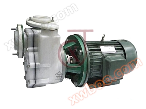
WFB type high-pressure high-power unsealed self-priming pump photographed at the user's site
2、 Working principle of WFB unsealed self-priming pump
Working principle: The main hydraulic components of a self-priming pump are the impeller and pump casing, which are similar to those of a general centrifugal pump. A liquid storage chamber and a gas water separation chamber are added to the pump chamber. WFB type unsealed self-priming pump, unsealed should be a secondary impeller power seal, also known as a fluid power seal. It can overcome some shortcomings of packing seals and mechanical seals, ensuring no leakage.
3、 Principle of dynamic sealing for the secondary impeller of WFB unsealed self-priming pump
The auxiliary impeller is located at the upper part of the working impeller and rotates together with the working impeller during operation. Its function is to reduce the pressure in the pump chamber, achieve balanced axial force, and prevent liquid from entering the sealing device. The secondary impeller actually relies on pressure to withstand the high-pressure liquid leakage at the outlet of the working impeller. When the pump is stopped, the secondary impeller does not work, so a shutdown seal should be equipped to prevent water from flowing out of the pump chamber.
4、 Structural diagram of high-pressure high-power unsealed self-priming pump

Column, 2. Lock and cap, 3. Working impeller, 4. Pump casing connection seat, 5. Spiral shell, 6. Pump shaft, 7. Lock and cap, 8. Sealing wheel cover plate, 9. Sealing seat, 10. Sealing impeller, 11. Pump casing outlet flange, 12. Bracket, 13. Motor, 14. Coupling, 15. Gasket A, 16. Gasket B, 17. Electric air valve, 18. Wear resistant ring, 19. Pump casing inlet flange, 20. Pump body, 21. Cone, 22. Pump casing suction flange, 23. Pump casing connection plate, 24. Bottom plate.
5、 Performance parameter table of WFB self controlled self-priming pump


Similar Product Recommend