-
E-mail
3305059282@qq.com
-
Phone
15926253748
-
Address
Economic-Technological Development Area
Product Categories
Wuhan Huading Power Equipment Co., Ltd
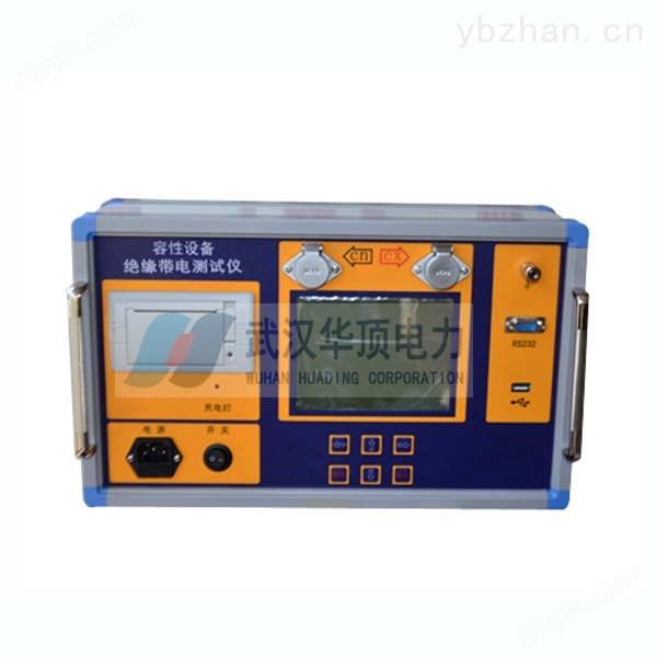
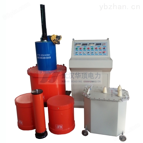
The power frequency modulation series resonance withstand voltage test device is easy to transport
NegotiableUpdate on 01/17
- Model
- Nature of the Manufacturer
- Producers
- Product Category
- Place of Origin
Overview
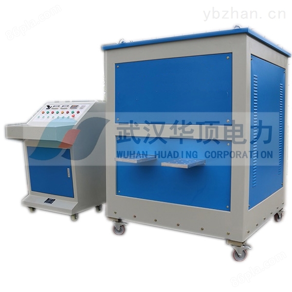
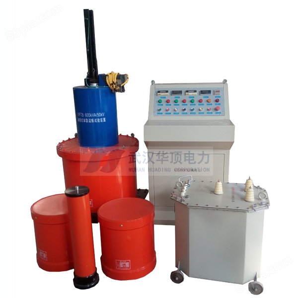
The manufacturer of the Inner Mongolia power frequency modulation series resonance withstand voltage test device, HDTP-50HZ power frequency modulation series resonance withstand voltage test device, is designed and manufactured as an adjustable resonance device for on-site verification of capacitive voltage transformers with a capacity of 500kV and below, and for AC withstand voltage testing of hydroelectric generators with a single capacity of 250MW. The reactor adopts a two separate design. Composed of variable frequency control power supply, excitation transformer, reactor, and capacitive voltage divider.
Product Details
1、 Product Introduction
The HDTP-50HZ series resonant withstand voltage test device is an adjustable resonant device used for on-site verification of capacitive voltage transformers of 500kV and below, and is designed and manufactured for AC withstand voltage testing of hydroelectric generators with a single capacity of 250MW. The reactor adopts a two separate design. Composed of variable frequency control power supply, excitation transformer, reactor, and capacitive voltage divider.
When calibrating a capacitive voltage transformer (CVT), the test frequency must be carried out at 50Hz. At the same time, the geographical conditions on site are complex, and traditional experimental devices are difficult to meet the requirements of on-site handling and testing. The tunable resonant boost device is an adjustable resonant device used for on-site calibration and has been widely used for on-site calibration of capacitive voltage transformers of 500kV and below in China.
The AC withstand voltage test of generators, such as thermal power generation units with a single unit capacity exceeding 1000MW and hydroelectric power generation units with a single unit capacity of 800MW; if traditional testing equipment (i.e. power frequency test transformers) is used for the AC power frequency withstand voltage test of these devices, due to the large capacity required for the test, the test transformers and regulators are very bulky, and the large capacity test power supply is also difficult to solve on site, making on-site testing extremely inconvenient. The power frequency resonance device has advantages in terms of test power capacity, equipment weight, test waveform, and investment. This device is mainly designed and manufactured for the AC withstand voltage test of hydraulic generators with a single unit capacity of 250MW and below.
Product Name: CVT Inspection Resonant Boosting Device, Variable Frequency Resonance, Variable Frequency Series Resonance, Series Resonance, Series Resonance Transformer, Series Resonance Boosting Device for Transformer Calibration, Series Resonance Test Equipment, Inductive Variable Frequency Resonant Voltage Endurance Device, Generator AC Voltage Endurance Harmonic Boosting Device
2、 Main features
1. Counterattack overvoltage and transmission overvoltage protection: This device uses proper wiring, complete protection links, and step-by-step energy absorption to prevent the harm of counterattack overvoltage and transmission overvoltage. After years of on-site practice, it has been proven that the test sample can avoid the damage and threat of overvoltage to the complete testing equipment and on-site testing personnel during flashover or breakdown. At the same time, it can also avoid the failure point of the test sample from not expanding the damage after flashover or breakdown.
2. Small size, light weight, easy installation and handling, simple wiring, very suitable for on-site personnel operation.
The main functions of the inductive resonance device are:
(1) Remote sensing function of reactor core gap:
This device is equipped with a gap sensor on the reactor, which can directly read the gap of the iron core on the control panel to guide operation. In addition, a gap limit switch and indicator are also installed.
(2) Voltage endurance time to automatic voltage reduction function:
The voltage endurance timer adopts a digital display timer. And when the withstand voltage time is reached, the system will automatically reduce the voltage
(3) Zero position closing and zero start boost function:
It has a zero position limit function. If the regulator is not at zero position, the high voltage output button cannot be closed, ensuring that the system is boosting from zero.
(4) Overcurrent protection function:
The system is equipped with an electromagnetic overcurrent relay, which has strong resistance and fast action, avoiding damage to the test sample caused by overcurrent.
(5) Overvoltage and subject flashover protection function:
This device is equipped with an electronic overvoltage flashover protection board to prevent the test sample from being damaged by overvoltage and flashover, and it operates quickly.
(6) Real time monitoring function for various experimental data:
It is possible to monitor the voltage and current on the high-voltage side and the low-voltage side, which can provide a more intuitive understanding of the experimental situation.
3、 Main technologies
| Rated output voltage | 0-50kV (AC RMS) adjustable parameter customization |
| output frequency | 45~65Hz |
| Resonant voltage waveform | Pure sine wave, waveform distortion rate ≤ 1.0% |
| working system | Under full power output, the general continuous working time is 5 minutes |
| Quality factors | 10~40 |
| Frequency regulation sensitivity | 0.1Hz, Instability<0.05% |
| Large experimental capacity | 5000kVA and below |
| working power supply | 220V or 380V ± 10%, power frequency 50Hz ± 5% |
Series product configuration (applicable scope (AC withstand voltage test for generators or motors with export voltage of 20kV and below, frequency: 50Hz ± 2Hz)
| Product model name | console | reactor | Incentive Transformer | Voltage divider | Applicable subjects |
| HDTP-50HZ- 50/50 | 10kW/220V | 50kV/1A per unit | 10kW/5kV | 50kV/500pF | Generator 0.07-0.13uF. 10kV cable (300mm)2)≤1.0km |
| HDTP-50HZ- 75/50 | 15kW/380V | 50kV/1.5A per unit | 15kW/5kV | 50kV/500pF | Generator 0.13-0.2uF. 10kV cable (300mm)2)≤1.5km |
| HDTP-50HZ - 225/50 | 25kW/380V | Two units of 50kV/1.5A. 50kV/1.5A per unit | 25kW/5kV | 50kV/500pF | Generator 0.2-0.27uF. 10kV cable (300mm)2)≤2.5km |
| HDTP-50HZ - 360/50 | 30kW/380V | Two units of 60kV/2A. 60kV/2A one unit | 30kW/5kV | 50kV/500pF | Generator 0.27-0.33uF |
| HDTP-50HZ- 200kVA/25kV | 30kW/380V | 30kVA (electric) | 200kVA/25kV adjustable one unit | 30kVA dry-type | 30kV | Hydroelectric generator. 0.4~1.0μF。 (10kV/40MW) |
| HDTP-50HZ- 300kVA/50kV | 60kW/380V | 60kVA (electric) | 300kVA/50kV adjustable one unit | 60kVA oil immersed type | 50kV | Thermal power generator. 0.27~0.33μF。 (20kV/300MW) |
| HDTP-50HZ- 600kVA/50kV | 60kW/380V | 60kVA (electric) | 200kVA/50kV adjustable one unit 400kVA/50kV adjustable one unit |
60kVA oil immersed type | 50kV | Thermal power generator. 0.113~0.45μF。 (20kV/600MW) |
| HDTP-50HZ- 1200kVA/50kV | 120kW/380V | 120kVA (induction) | Two fixed 200kVA/50kV units 800kVA/50kV adjustable one unit |
120kVA oil immersed type | 50kV | Hydroelectric generator. 0.6~1.8μF。 (20kV/250MW) |
| HDTP-50HZ- 2750kVA/55kV | 300kW/380V | 300kVA (induction) | 750kVA/55kV fixed two units 1250kVA/55kV adjustable one unit |
120kVA oil immersed type | 60kV | Hydroelectric generator. 1.6~3.3μF。 (20kV/770MW) |
Introduction to the configuration of commonly used power frequency resonance devices
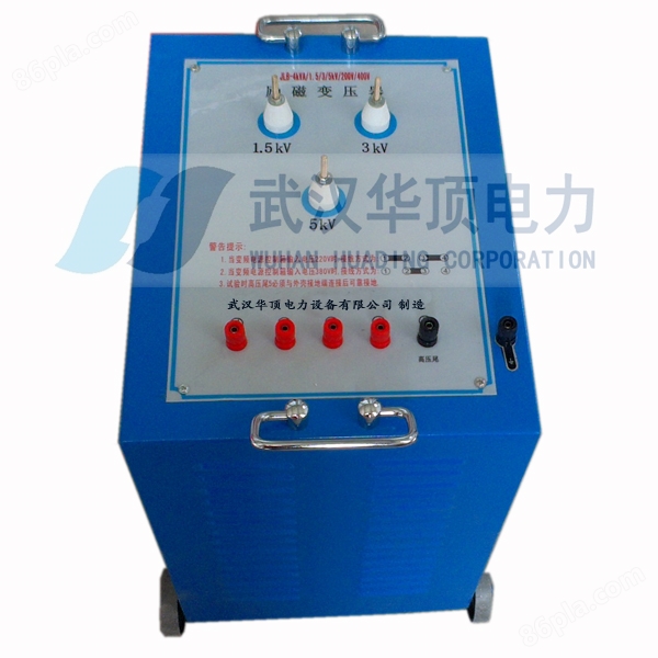
1. Excitation transformer HDLB-80kVA/4/5/6kV 1 set
A: Rated capacity: 80kVA;
B: Input voltage: 400V, single-phase;
C: Output voltage: 4/5/6kV
D: Structure: Dry type;
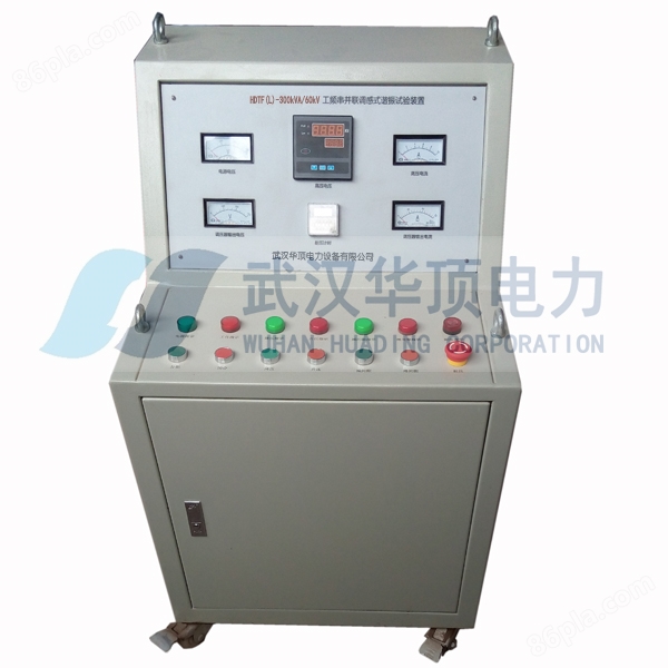
2. Console HDCT-80kVA/380V 1 unit
A: Rated capacity: 80kVA;
B: Input voltage: 380V;
C: Output voltage: 0~400V;
D: Protection function: zero position, overcurrent, overvoltage, and test sample flashover protection;;
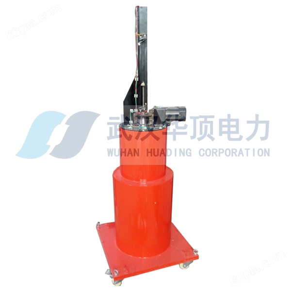
3. One adjustable reactor HDTB-k-200kVA/50kV
A: Rated capacity: 200kVA
B: Rated voltage: 50kV;
C: Rated current: 4A;
D: Inductance: 25~100H
E: Quality factor: Q ≥ 40;
F: Structure: Dry adjustable;
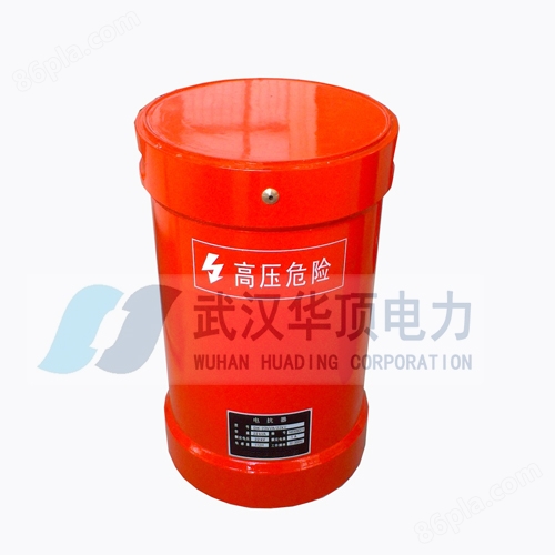
3. Three fixed reactors HDTB-G-200kVA/50kV
A: Rated capacity: 200kVA
B: Rated voltage: 50kV;
C: Rated current: 4A;
D: Inductance: 25H * 2 units/35H * 1 unit
E: Quality factor: Q ≥ 40;
F: Structure: Dry adjustable;
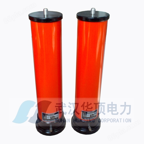
4. One HDFCR-50kV capacitive voltage divider
A: Rated voltage: 50kV;
B: Measurement accuracy: AC effective value of 1.5 level;
C: Dielectric loss: Tg σ ≤ 0.5%;
D: Voltage division ratio: 1000:1, voltage division ratio error: ≤ 1.0%;
For more details, please follow Wuhan Huading Power Equipment Co., Ltd
Insulation resistance and absorption ratio test
The insulation resistance of measuring equipment is an auxiliary method for checking its insulation status. A megohmmeter is commonly used on site to measure insulation resistance. Due to the use of a megohmmeter with a voltage lower than the working voltage of the test substance, this test is a non-destructive test that is safe and easy to operate. The measured insulation resistance value can reveal defects such as foreign objects affecting the insulation of electrical equipment, local or overall moisture and dirt in the insulation, severe aging of insulation oil, insulation breakdown, and severe thermal aging. Therefore, measuring insulation resistance is a basic method that testers should master during electrical installation, maintenance, and operation.
Insulation resistance and absorption ratio
Insulation resistance refers to the ratio of the direct current voltage applied to the test sample to the leakage current (or conductivity current) flowing through the test sample at the critical voltage of the insulator, that is, R=U/Ie. If the applied direct current voltage exceeds the critical voltage value of the insulator, conductivity current will be generated, and the insulation resistance will sharply decrease. Therefore, under the action of high voltage, insulation will be damaged, and even breakdown may occur. So the rated voltage of a general megohmmeter is not too high, and insulation should be selected according to different voltage levels when using it.
The insulation medium used in engineering is not purely an insulator. Under the action of DC voltage, various polarizations will occur, and it takes a certain amount of time from the beginning to the completion of polarization. Usually, the relationship between insulation resistance and time is used as the basis for judging the insulation state.
After applying a direct current voltage on an insulator, three types of currents are generated, namely conduction current, capacitance current, and absorption current. The changes in these three currents can reflect the magnitude of the insulation resistance value, that is, as the pressurization time increases, the sum of these three current values decreases, while the insulation resistance value increases accordingly. For large capacity equipment with interlayer insulation (such as transformers, cables, motors, etc.), this absorption phenomenon is more obvious. Because the total current decays over time and only approaches the value of the conductive current after a certain period of time, it is usually required to read the value of the megohmmeter after applying pressure for 1 minute in order to represent the true insulation resistance value. When the insulation of the test sample is damp, dirty, or has penetrating defects, the ions in the medium increase, resulting in a significant increase in conductivity current and a significant decrease in insulation resistance after pressurization. The insulation resistance value can sensitively reflect these insulation defects, achieving the goal of preliminary understanding of the insulation state of the test sample. However, due to the fact that the insulation resistance value of the test sample is not only determined by the degree of moisture and surface contamination of the test sample, but also related to many complex factors such as its size, material, manufacturing process, capacity, etc., there is no unified specific regulation for the value of insulation resistance. In addition, the value of insulation resistance of the same test substance is greatly affected by external factors such as temperature, humidity, etc. Therefore, it is difficult to determine the insulation state from a single measurement result. It is necessary to compare the results of previous measurements under similar conditions in order to make a judgment.
2Absorption ratio
Due to the absorption phenomenon in dielectrics, in practical applications, the ratio of the insulation resistance value measured at 60 seconds of pressure to the insulation resistance value measured at 15 seconds of pressure is called the absorption ratio, that is, K=R60/R15. For the absorption ratio, because it measures the ratio of two resistances or two currents, its value is not significantly related to factors such as the size, material, and capacity of the test sample, and is less affected by other accidental factors. It can accurately reflect the moisture condition of the insulation of the test sample. In a well insulated state, its leakage current is generally small, but the absorption current is relatively large (R15 is small), and the absorption ratio K value is large; When there is a defect in the insulation, the polarization of the dielectric is strengthened, the absorption current increases, but the increase in leakage current is more significant (R60 is smaller), and the K value decreases and approaches 1. So, based on the absorption ratio, especially by comparing the measurement results with those obtained under the same conditions before, the degree of insulation can be judged. However, this test is only applicable to samples with large capacitance, such as transformers, cables, motors, etcManufacturer of Inner Mongolia power frequency modulation series resonant withstand voltage test deviceThe sample with a small capacitance has no practical value due to insignificant absorption phenomenon.
Test method
Disconnect the power supply of the test sample and remove all external connections, ground it and discharge it fully. The discharge time should not be less than 1 minute. For test samples with large capacitance (such as transformers, capacitors, cables, etc.), the discharge time is generally not less than 2 minutes. If encountering repeated tests or samples subjected to high DC voltage, the discharge time should be longer. Insulation tools (such as insulation rods, insulation gloves, insulation pliers, etc.) should be used for discharge workManufacturer of Inner Mongolia power frequency modulation series resonant withstand voltage test deviceYou have to directly touch the discharge wire with your hands.
Wipe off the dirt on the surface of the test sample with a clean and soft cloth, and if necessary, clean the accumulated dirt on the surface of the sleeve with gasoline or other suitable descaling agents first.
Similar Product Recommend