-
E-mail
hushanfamen@126.com
- Phone
-
Address
No.2 Xincheng Road, Nicheng Town, Pudong New Area, Shanghai
Product Categories
Hushan Valve Manufacturing (Shanghai) Co., Ltd
Q944 (5) electric three-way ball valve
NegotiableUpdate on 05/21
- Model
- Nature of the Manufacturer
- Producers
- Product Category
- Place of Origin
Overview
2、 Electric three-way ball valve execution standard
Product Details
| product name: | Electric three-way ball valve | PRODUCT MODEL: | Q944(5) |
| Drive mode: | Electric | Connection form: | flange |
| structural style: | three direct links | Sealing material: |
Polytetrafluoroethylene (PTFE) |
| Pressure range: | 1.6MPa | Nominal Diameter: | DN10-DN65 |
| Common materials: | Carbon steel, stainless steel | technical advice: |
1、 Overview of Electric Three way Ball Valve
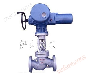
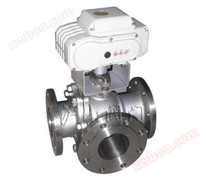
Q944(5)Electric three-way ball valveIntelligent by CHR seriesElectric actuatorComposed of a three-way ball valve, it is a rotary cut-off regulating valve with advantages such as tight closure, compact structure, light weight, and easy maintenance. Widely used in pipeline automation control of corrosive media such as gases, liquids, vapors, and oils.
The two seat sealed three-way ball valve has a compact structure, beautiful appearance, and good sealing performance. It can switch the flow direction of the medium in the pipeline. It can also connect or close two perpendicular channels.
The four seat sealed three-way ball valve has a beautiful appearance and a compact and reasonable structure. It can not only switch the flow direction of the medium, but also connect the three channels to each other. Currently, it can also close any channel and connect the other two channels, flexibly controlling the merging or splitting of the medium in the pipeline.

2、 Electric three-way ball valve execution standard
1. Design and Manufacturing: GB/T12237-1989; APl608
2. Inspection and testing: GB/T13927-1992; APl 598
3. Flange connection: JB/T79; ASME/ANSI B165
4. Structural length: JB-12221
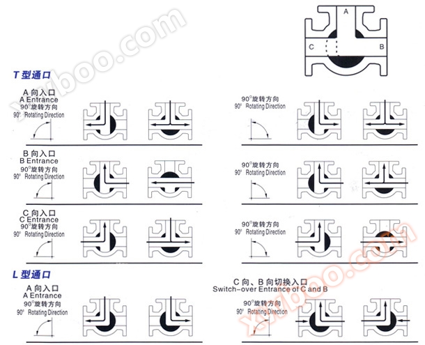
3、 Schematic diagram of flow direction for electric three-way ball valve
Three way ball valves are divided into L-shaped and T-shaped, and the direction of medium flow is shown in the following figure. The L-shaped three-way ball valve is suitable for switching the flow direction of the medium, which can connect two perpendicular channels. The T-shaped three-way ball valve is suitable for dividing, merging or switching the flow direction of the medium. The T-shaped hole can connect three channels to each other or two of them. The three-way ball valve generally adopts a two seat structure, but can also adopt a four seat structure according to user requirements.
4、 Main technical indicators of electric three-way ball valve
Control accuracy: adjustable from 0.1% to 3.1%.
Accepting control signals: 0-10mA.DC, 4-20mA.DC, or 1-5V.DC.
Key selection: 1. When the input signal is interrupted: "Interrupt" mode (on, stop, off) 2. Selection of forward and reverse actions 3. Selection of control accuracy.
Automatic positioning and calibration of the fully open and fully closed positions of the electric device, convenient and accurate.
Intelligent step distance adjustment and automatic positioning based on input signal and electric device position, with high precision in suppressing oscillation.
Output electric device position signal: 4-20mA.DC corresponds to fully closed or fully open electric device.
5、 Electric three-way ball valve material
|
1) Shaft axis |
Stainless steel ANSI316 | 1.4401 | UNIX5CrNiMo 17 12 |
|---|---|---|---|
|
2) Lock nut |
Stainless steel ANSI304 |
1.4301 |
UNIX5CrNi 18 10 |
|
3) Tighten the ring nut Gland nut ring |
Stainless steel ANSI304 |
1.4301 |
UNIX5CrNi 18 10 |
|
4) Top sealing ring to p tight ring |
Polytetrafluoroethylene (PTFE) |
|
|
|
5) O-Ring |
Fluororubber VITON |
|
|
|
6) Washer washer |
Polytetrafluoroethylene (PTFE) |
|
|
|
7) Sealing rings |
Polytetrafluoroethylene (PTFE) |
|
|
|
8) Valve Body |
Stainless steel ANSI316 |
1.4408 |
|
|
9) Ball valve |
Stainless steel ANSI316 |
1.4401 |
UNIX5CrNiMo 17 12 |
|
10) Top sealing End sealing |
Polytetrafluoroethylene (PTFE) |
|
|
|
11) End End |
Stainless steel ANSI316 |
1.4408 |
|
|
12) Flange |
Stainless steel ANSI316 |
1.4408 |
|
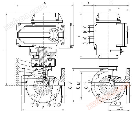
6、 Specification and dimensions of electric three-way ball valve
|
|
| Structural diagram of electric three-way ball valve |
|
DN |
mm. | 10 | 15 | 20 | 25 | 32 | 40 | 50 | 65 |
|---|---|---|---|---|---|---|---|---|---|
|
Internal thread size |
GAS |
3/8' |
1/2' |
3/4' |
1' |
1'1/4 |
1'1/2 |
2' |
2'1/2 |
|
orifice |
mm. |
10 |
15 |
20 |
25 |
32 |
40 |
50 |
65 |
|
P. Valve |
PN40 |
PN40 |
PN40 |
PN40 |
PN40 |
PN40 |
PN25 |
PN25 |
PN25 |
|
A |
mm. |
207,5 |
207,5 |
207,5 |
207,5 |
256,5 |
256,5 |
256,5 |
256,5 |
|
B |
mm. |
122,5 |
122,5 |
122,5 |
122,5 |
156,5 |
156,5 |
156,5 |
156,5 |
|
C |
mm. |
68 |
68 |
68 |
68 |
94 |
94 |
94 |
94 |
|
D |
mm. |
163,5 |
163,5 |
163,5 |
163,5 |
185 |
185 |
185 |
185 |
|
X |
mm. |
44 |
44 |
44 |
44 |
44 |
44 |
44 |
44 |
|
E |
mm. |
120 |
130 |
140 |
150 |
180 |
200 |
220 |
240 |
|
ΦG |
mm. |
90 |
95 |
105 |
115 |
140 |
1450 |
165 |
185 |
|
ΦM |
mm. |
60 |
65 |
75 |
85 |
100 |
110 |
125 |
145 |
|
ΦN |
mm. |
14/4 |
14/4 |
14/4 |
14/4 |
18/4 |
18/4 |
18/4 |
18/4 |
|
H |
mm. |
249,5 |
252,5 |
260 |
264,5 |
304,5 |
312 |
275,5 |
284,5 |
|
T. of cycle 50/60 Hz |
s. |
15 / 12,5 |
15 / 12,5 |
15 / 12,5 |
15 / 12,5 |
15 / 12,5 |
15 / 12,5 |
15 / 12,5 |
15 / 12,5 |
|
weight |
Kg. |
8,1 |
8,6 |
10,1 |
11,5 |
20,5 |
23,7 |
28 |
32,6 |