-
E-mail
3305059282@qq.com
-
Phone
15926253748
-
Address
Economic-Technological Development Area
Product Categories
Wuhan Huading Power Equipment Co., Ltd
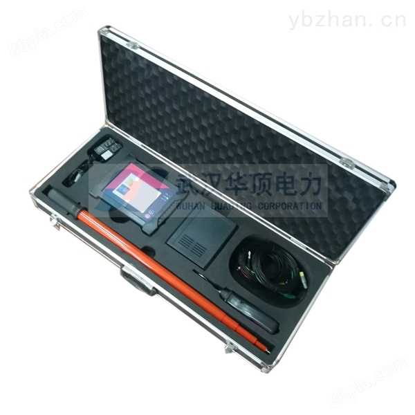
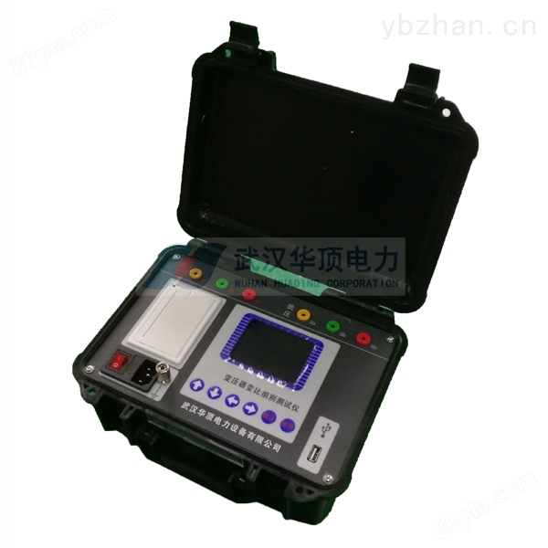
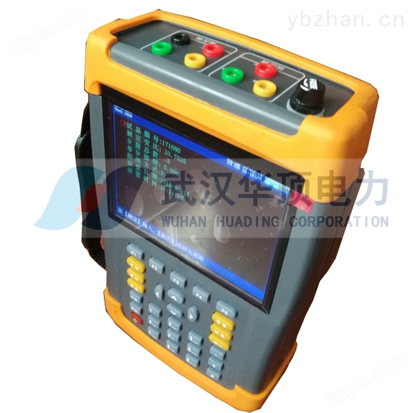
Handheld Transformer Ratio Group Tester by Huading Power is Suitable for Field Operations
NegotiableUpdate on 01/17
- Model
- Nature of the Manufacturer
- Producers
- Product Category
- Place of Origin
Overview
The principle of Tangshan handheld transformer ratio group tester is true three-phase testing: single-phase power input, internal digital synthesis of three-phase standard sine wave signal source, through high fidelity power amplifier, generates three-phase test power (distortion less than 0.1%, symmetry better than 0.05%) output, the test results have better equivalence, and there will be no group misjudgment or other phenomena.
Product Details
Functional Features
1. True three-phase testing: single-phase power input, internal digital synthesis of three-phase standard sine wave signal source, through high fidelity power amplifier, generates three-phase test power output (distortion less than 0.1%, symmetry better than 0.05%), the test results have better equivalence, and there will be no group misjudgment or other phenomena.
2. Powerful function: It can perform single-phase measurement and automatic testing of three-phase windings. Both single-phase and three-phase can measure polarity and phase angle. It can complete the measurement of AB, BC, CA three-phase transformation value, phase angle value, error, tap position, tap value and other parameters in one go, and can automatically identify the group number.
3. Phase angle measurement function: Accurately measure the phase angle between the high and low voltage sides, and can measure the transformation ratio and angle of non integer point transformers.
4. Hexagonal diagram display function: The test results are displayed in numerical and hexagonal vector diagrams, which intuitively show the connection group of the transformer.
5. Blind testing function: No need to select the wiring method or wiring group, measuring Y/△ and △/Y transformers does not require external short circuiting, and the wiring method can be automatically switched according to the selected testing content. *It is possible to measure the transformation ratio and group number of transformers without nameplates.
6. Tap test: It can quickly measure the transformation ratio and transformation ratio error at each tap switch position. The rated transformation ratio only needs to be input once, and the transformation ratio error at each tap position can be calculated without repeated input.
7. At the same time, it has two functions: measuring the turns ratio and measuring the operating voltage transformation ratio. The operating transformation ratio can more accurately reflect the actual value of the voltage transformation ratio of the transformer in actual operation.
8. Good anti vibration performance: The use of connectors enhances the anti vibration performance.
9. Adopting a 5.6-inch high-definition true color LCD screen, the display of data and vector graphics is intuitive and delicate.
10. The test source used for the HDB-III handheld transformer ratio group tester is a standard sine digital source synthesized digitally, with a distortion of less than 0.1%, and is not affected by the quality of the working power supply.
11. Convenient to carry: small size and light weight. The models of measuring transformers include Z-type transformers, Scott, and three-phase group ratio measurement.
12. Internally equipped with high-capacity lithium-ion rechargeable batteries, the testing work can be completed on site without any power supply. With one full charge, it can perform more than 800 consecutive measurements.
2、 Technical indicators
1. Variable ratio measurement range: 0.8~10000.
2. Fast measurement speed: Complete three-phase testing within 1 minute.
3. Measurement accuracy: The measurement accuracy of the high voltage side voltage is 0.05%
The measurement accuracy of low-voltage side voltage is 0.1%
Phase angle measurement accuracy: 0.1 °
Variable ratio measurement accuracy 0.1% (0.8-3000)
0.2%(3000-10000)
According to user requirements, equipment with a full range of 0.1 level can be customized
4. Convenient to carry and suitable for field operations.
5. Weight: 3Kg

Compared to. If the total length of the cable is L and the distance between the broken points of the core wire is X, then Ia/Ic=L/X, and X=(Ic/Ia) L.
During the measurement process, as long as the voltage remains constant, the ammeter reading is accurate, and the total cable length measurement is precise, the measurement error is relatively small.
(4)Zero potential method:
The zero potential method, also known as the potential comparison method, is suitable for short cable core wire to ground faults. This method is easy and accurate to measure, without the need for precision instruments or complex calculations. Its wiring is shown in Figure 5, and the measurement principle is as follows: parallel the cable fault core wire with an equally long comparison wire. When a voltage E is applied at both ends, it is equivalent to connecting a power source at both ends of two parallel uniform resistance wires. At this time, the potential difference between any point on one resistance wire and the corresponding point on another resistance wire must be zero. On the contrary, the two points with zero potential difference are necessarily corresponding points. Because the negative pole of the microvoltmeter is grounded and at the same potential as the cable fault point, when the positive pole of the microvoltmeter moves on the comparison wire to the point where the indicated value is zero, it is at the same potential as the fault point, that is, the corresponding point of the fault point.
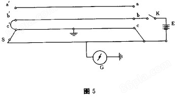
In the figure, K is a single-phase knife switch, E is a 6V battery or 4 No. 1 dry batteries, and G is a DC micro voltmeter. The measurement steps are as follows:
① First, connect battery E to the core wires of phases b and c, and then lay a comparison wire S on the ground that is the same length as the faulty cable. The wire should be made of bare copper or bare aluminum wire, with equal cross-sections and no intermediate joints.
②Ground the negative pole of the microvolt meter and connect the positive pole to a longer onePrinciple of Handheld Transformer Ratio Group Tester in Tangshan CityThe flexible wire requires sufficient contact at the other end when sliding on the laid comparative wire.
③Close the knife switch K and slide the end of the flexible wire on the comparison wire. The position where the micro voltmeter indicates zero is the location of the cable fault point.
Other methods for diagnosing and locating faults in power cables:
1Types of faults
Power cables can malfunction due to mechanical damage, insulation aging, low construction quality, overvoltage, and loss of insulation oil. According to the nature of the fault, it can be divided into low resistance grounding or short circuit fault, high resistance groundingPrinciple of Handheld Transformer Ratio Group Tester in Tangshan CityGround or short circuit faults, wire breakage faults, wire breakage and grounding faults, and flashover faults.
2Methods for diagnosing faults
The method to determine the type of cable fault is to use a megohmmeter to measure the insulation resistance of each phase at one end of the line. Generally, the type of fault is determined based on the following situations:
Similar Product Recommend