-
Phone
13676799385
-
Address
No. 8 Linpu Road, Zhangbao Industrial Zone, Oubei Town, Yongjia County, Zhejiang Province
Product Categories
Yongjia County Marine Water Pump Factory
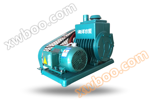
2X Double stage Oil Seal Mechanical Vacuum Pump
NegotiableUpdate on 09/20
- Model
- Nature of the Manufacturer
- Producers
- Product Category
- Place of Origin
Overview
The 2X two-stage oil sealed mechanical rotary vane vacuum pump is a basic equipment used to extract gas from sealed containers and obtain vacuum. Its working principle is the same as that of a general vacuum pump. It is composed of a rotor installed in the same core as the transmission shaft and in an eccentric position inside the pump body. There are two radial sliding blades on the rotor. When the rotor rotates, these two blades are subjected to centrifugal force on one hand and spring force on the other, allowing them to tightly maintain a distance from the inner wall of the pump body and compress and discharge gas, thereby achieving the purpose of pumping. This operation is repeated twice per rotation
Product Details
Model Meaning
Product Overview
The 2X two-stage oil sealed mechanical rotary vane vacuum pump is a basic equipment used to extract gas from sealed containers and obtain vacuum. Its working principle is the same as that of a general vacuum pump. It is composed of a rotor installed in the same core as the transmission shaft and in an eccentric position inside the pump body. There are two radial sliding blades on the rotor. When the rotor rotates, these two blades are subjected to centrifugal force on one hand and spring force on the other, allowing them to tightly maintain a distance from the inner wall of the pump body to compress and discharge gas, thereby achieving the purpose of pumping. This operation is repeated twice per rotation.
It is particularly noteworthy that the 2X-4B two-stage rotary vane vacuum pump designed and manufactured by our factory has changed the appearance of old products from the 1930s in China, and has taken the lead in the market with its unique and excellent performance. The pump has the following characteristics:
1: The advantages include fast pumping speed, small size, light weight, low noise, easy maintenance, and high ultimate vacuum degree. According to the national standard, the vacuum limit is 6 * 10-2Pa (i.e. 5 * 10-4Torr, note: Torr=133.32Pa), while the limit vacuum degree of our factory's 2X-4B two-stage rotary vane vacuum pump is 4 * 10-2Pa (i.e. 3 * 10-4Torr), which is 0.2 orders of magnitude higher than the international vacuum degree and can achieve your ideal vacuum degree in a very short time.
2: There is a reliable dust prevention device. Other rotary vane pumps can be connected to the pump chamber when debris passes through the dust prevention device. And when debris passes through the dust prevention device, the 4B pump can only flow around the outside of the dust prevention device. This ensures the normal operation of the pump and completely solves the problem of debris entering the pump chamber and biting.
3: There is a composite screw with an air release valve and an oil inlet hole. The two-stage rotary vane pumps produced in our country for many years have oil inlet holes designed on the low-level exhaust valve seats inside the oil tank. When the oil hole is blocked, it is necessary to drain the oil and remove the fuel tank in order to clear the oil hole. The pump only needs to unscrew the composite screw to clear the oil hole and discharge debris and water vapor. It is both fast and labor-saving, greatly improving the working efficiency of the pump.
Another new product worth introducing is the 2X-New 4A two-stage rotary vane vacuum pump, which also has unique and excellent features:
1: Small size, compact structure, light weight, 6 kilograms lighter than similar products.
2: Fast pumping speed, high vacuum degree, and can directly extract air from atmospheric pressure.
3: It can be used alone as a low vacuum pump or combined with other high vacuum pumps as a front-end pump.
4: The design of the exhaust hood structure is reasonable and can capture oil fumes, thus eliminating fuel spraying, reducing environmental pollution, and saving oil.
Therefore, the 2X-New 4A dual stage rotary vane vacuum pump is widely used in various industries, universities, and research institutions, and is an ideal choice for users.
Scope of application
1: The 2X two-stage oil sealed mechanical vacuum pump system is a basic equipment for extracting gases. It can be used alone or connected with ultra-high vacuum pumps such as booster pumps and molecular pumps as a front-end pump. It is widely used in electronic device manufacturing, vacuum drying, filtration, immersion, coating, welding, smelting, chemical industry, light industry, petroleum, medical, pharmaceutical, printing and dyeing, electric vacuum, semiconductor, food, atomic energy, textile and other scientific research institutions, colleges and universities, industrial and mining enterprises.
2: The pump is allowed to operate for a long time within the ambient temperature range of 5 ℃ -40 ℃ and the inlet pressure is less than 1.3 * 103 Pa. When the relative humidity of the extracted gas is greater than 90%, the gas damper should be opened.
3: The continuous smooth operation of the pump inlet under atmospheric conditions shall not exceed 3 minutes.
4: Pumps are not suitable for extracting gases that are corrosive to metals, chemically react with pump oil, contain particulate dust, or contain explosive or toxic gases with high oxygen content.
Principle and Structure
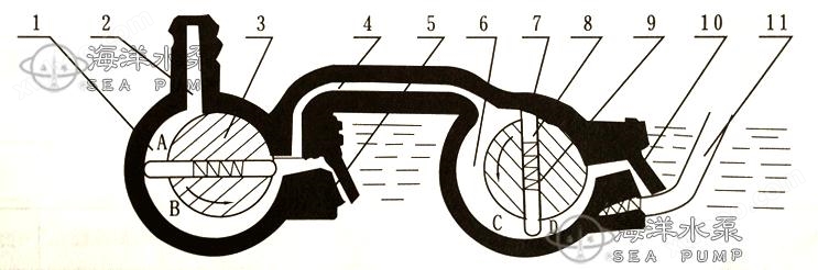
Figure 1 is the schematic diagram of the 2X two-stage oil sealed mechanical vacuum pump system. The rotors 3 and 7 are tangent to the high vacuum chamber 1 and the low vacuum chamber 6. The rotors 3 and 7 rotate in the direction of the arrows, driving the rotating blades that slide in the rotor groove to rotate. Due to the action of the spring 9 and centrifugal force, the outer end of the rotating blades slides tightly against the inner surface of the high and low vacuum chambers, separating the moon shaped space formed by the rotor and the high and low vacuum chambers from the intake nozzle 2 to the exhaust valve 5 and from the exhaust pipe 4 to the exhaust valve 10, forming two or three volumes with periodic size changes. When continuing to rotate at the position shown in the figure, the volumes A and C gradually increase, and the gas being pumped enters through the intake nozzle without entering. Inside the pump, both B and D The volume gradually decreases, the pressure increases, and then the exhaust valves 5 and 10 are opened to discharge the gas outside the vacuum chamber. The gas passes through the oil surface and is discharged into the atmosphere. Because the oil floods the exhaust valve, it can prevent the gas from returning to the vacuum chamber. When the pumping pressure is high, the valves of both the high and low vacuum chambers exhaust, equivalent to a single-stage pump. When the vacuum degree is high, all the gas enters the vacuum chamber and is then discharged through exhaust valve 10. At this time, the two-stage series connection enters the operation of the two-stage pump.
 |
|||||||||
Figure 1 |
|||||||||
1 |
高真空室外 |
2 |
Intake nozzle |
3 |
rotor |
4 |
Gas tube |
5 |
Exhaust valve |
6 |
Low vacuum chamber |
7 |
rotor |
8 |
scraper |
9 |
spring |
10 |
Exhaust valve |
When the extracted gas contains a high amount of vapor gas, when the gas is compressed and the partial pressure of its vapor exceeds the saturation pressure of the vapor at the pump temperature, the vapor is compressed into a liquid, which cannot be discharged by the vacuum pump and mixes with the vacuum oil, greatly reducing the performance of the pump. If an appropriate amount of air is added, so that the partial pressure of the steam when compressed is also lower than the saturation pressure of the pump temperature, the steam can be discharged from the pump before becoming liquid. Therefore, pumps above 2X-4 in this series are equipped with a gas mixing valve 11 that can accommodate a certain amount of gas, as shown in Figure 1
The appearance and structure of various vacuum pumps in the 2X series are basically the same, and the pump is driven by a motor through a V-belt to the rotor. The electric motor and pump are fixed to the chassis with screw clamps. The pump consists of pump body, high rotor, low rotor, front end plate, rear end plate, high rotor, low rotor, exhaust valve, exhaust hood, sight glass and other components. Refer to Figures 2 and 3. A middle partition is pressed into the pump body to divide the pump casing into high and low vacuum chambers, each of which has an exhaust valve. The exhaust of the high vacuum chamber is connected to the low vacuum air. The front end of the high rotor extends out of the front axle; Extend the rear axle from the rear end. The front axle is supported by the bearings on the front end plate and extends outside the front end plate through the oil seal chamber, while the rear axle is supported by the bearings on the middle partition plate. And when extending into the low vacuum chamber, the low vacuum chamber rotor is mounted on the rear axle, so both the high and low rotors are driven by the front axle. Both the high and low rotors have opposite slots, and the T-shaped rotating blades are supported by springs and installed in the slots. There is a filter screen at the inlet of the pump, and an oil blocking screen at the outlet. There is a mixing valve on the left side of the sight glass and an oil drain plug below.
|
||||||||||||||
Figure 2 |
||||||||||||||
Gas pathway |
3 |
filter screen |
8 |
a pellet shot from a slingshot |
13 |
Exhaust hood |
18 |
Back end board |
23 |
Water cover plate |
||||
-- → High vacuum path |
4 |
pulley |
9 |
front axle |
14 |
Exhaust hood gasket |
19 |
Low rotor |
24 |
Exhaust valve plate |
||||
-- → High vacuum path |
5 |
Front end board |
10 |
Oil sealed chamber |
15 |
Oil blocking net |
20 |
Cooling water connection |
25 |
Windows |
||||
1 |
Intake nozzle |
6 |
High conversion film |
11 |
spring |
16 |
pump casing |
21 |
key |
26 |
aerification valve |
|||
2 |
sealing ring |
7 |
High rotor |
12 |
Positioning pin |
17 |
partition |
22 |
Bottom rotor |
27 |
drain plug |
|||



|
|||||||||||||
Fig 3 |
|||||||||||||
1 |
pulley |
6 |
Exhaust nozzle |
11 |
Low rotor |
16 |
steel ball |
21 |
valve plate |
||||
2 |
key |
7 |
sealing ring |
12 |
spring |
17 |
handle |
22 |
Barrier board |
||||
3 |
Front end board |
8 |
Exhaust hood |
13 |
Bottom rotor |
18 |
drain plug |
23 |
oiled-paper umbrella |
||||
4 |
High rotor |
9 |
filter screen |
14 |
Back end board |
19 |
paper pad |
24 |
Positioning pin |
||||
5 |
High conversion film |
10 |
pump body |
15 |
spring |
20 |
valve seat |
||||||




The oil in the oil sealed chamber is supplied from oil tank A through the holes on the front end plate. The oil in the low vacuum chamber is supplied from oil tank A through the holes on the rear end plate. The oil in the high vacuum chamber is supplied cyclically through the holes on the middle partition. The sealing of the front and rear end caps is achieved by the oil pool B on the upper part of the pump body flowing into the oil groove through the hole in the end face chamber of the pump body for sealing.
performance parameters
| model | 2X -2 | 2X -4A | 2X-8A | 2X-8 | 2X-15A | 2X-15 | 2X -30 | 2X -70 | Remarks | |
| Extraction rate L/S | 2 | 4 | 8 | 15 | 30 | 70 | Using seat type compression mercury Vacuum gauge measures at the pump port Use thermocouple meter and resistance meter Wait for the total pressure gauge volume. for reference only |
|||
| ultimate vacuum Pa |
Guanqi Town | 6×10⁻²(≤5×10⁻⁴)110 | ||||||||
Kaiqi Town |
6×10⁻¹(5×10⁻³) | (≤1×10⁻²) |
||||||||
| Motor power Kw | 0.37 | 0.55 | 1.1 | 1.5 | 3 | 5.5 | ||||
| Temperature rise ℃ | ≤40℃ | |||||||||
| Noise dB (A) | 68 | ≤ 68 |
≤ 70 | ≤ 75 | ≤ 78(~70) | ≤ 80(~75) | ||||
| Inlet diameter mm | 18 | 25 | 40 | 40 | 65 | 80 | ||||
| RPM (revolutions per minute) | 450 | 590 | 420 | |||||||
| Oil consumption L | 0.7 | 1.0 | 2.0 | 2.8 | 3.0 | 4.2 | No.1 vacuum pump oil | |||
| Applicable solenoid valve models | DDC-JQ25 | DDC-JQ40 | DDC-JQ65 | DDC-JQ80 | ||||||
| Weight kg | 58 | 55 | 80 | 110 | 232 | 330 | ||||
| cooling method | natural cooling | water cooling | natural cooling | water cooling | ||||||
| Cooling water volume L/min | - | - | >0.5 | - | >0.8 | >1 | >2 | |||
(2) The pumping speed is calculated based on geometric dimensions. At atmospheric pressure j, the actual pumping speed is basically consistent with the geometric pumping speed. At various pressures, the pumping speed decreases to some extent. The relationship between pumping speed and pressure is shown in Figure 4.
(3) Temperature rise refers to the difference between the temperature of the oil at the exhaust valve and the room temperature after the pump temperature stabilizes.
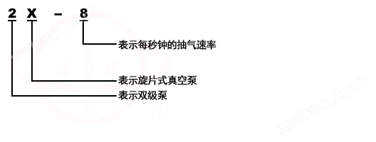
(4) Model representation method: Column 2K-1,2 represents a two-stage pump, K represents a rotary vane vacuum pump, and the number after a horizontal line represents the pumping speed per second.
Sexual parameter curve
|
||||
Figure 4 |




Unpacking and installation
|




1. After unpacking, carefully remove the vacuum pump body, spare accessories, and instruction manual. Remove the filling material and clean the surface dust and dirt of the pump. Count the quantity according to the packing list.
2. The rotary vane vacuum pump is installed in an indoor environment that is clean, well ventilated, and has sufficient light to meet the requirements of Article 4. According to usage, the pump should be installed in a spacious area for easy operation and maintenance. The external dimensions of the rotary vane vacuum pump are shown in. It can be placed on a solid and flat ground without the need for a special foundation. If it needs to be fixed, additional screws can be added to secure it firmly to the foundation. The size of the anchor screws is shown in. When using rotary vane vacuum pumps close to precision instruments, consideration should be given to adding shock-absorbing devices.
3. The container to be pumped should be connected to the rotary vane vacuum pump using a vacuum hose or flange. If a flange is used for connection, there should be a rubber ring groove on the flange, with the form and size shown in the above figure. The diameter of the pipe connecting the container to be pumped should not be smaller than the diameter of the pump inlet. The pipe should be short and the joints should be few, otherwise it will affect the pumping speed. The air leakage of the pipeline and joints should be small The amount of gas in the container being pumped should be adapted to the pumping speed of the pump. It is recommended to install a vacuum valve between the pump and the container being pumped to control the gas flow rate. For the pump, it is recommended to install a vent valve (or solenoid valve) to release air during parking, which can prevent oil return and make it easy to start.
4. Connect the power supply according to the voltage and wiring method indicated on the motor label, and it is recommended to use a safety device to prevent overload. Determine the direction of rotation of the motor, which should be consistent with the direction of the arrow on the rotary vane vacuum pump. Remove the exhaust plug and install the exhaust hood, or remove the sleeve from the exhaust nozzle. The rotary vane vacuum pump requires the cooler to be connected to a water source.
5. If it is necessary to use the 2X rotary vane vacuum pump to remove toxic and corrosive gases that corrode black metals, gases that cause chemical changes in vacuum oil, and gases that exceed room temperature and have dust, relevant devices such as neutralization, cooling, and filtration should be installed on the intake pipeline to cooperate with use, otherwise it will affect the performance and service life of the rotary vane vacuum pump. When extracting harmful gases to the human body, corresponding pipelines should be installed to direct the exhaust gas outdoors away from the work area for treatment.
Note: Be careful during installation to prevent iron filings, dirt, dust, etc. from falling into the rotary vane vacuum pump
Instructions for Use
1. Precautions for the operation of rotary vane vacuum pump:
(1) Start intermittently 1-2 times, observe for any abnormal sounds or special vibrations during operation, and only continue running if there are no issues.
(2) Note that the oil level should be between the two oil markings on the sight glass. Excessive oil level can cause difficulties in starting, oil return, fuel injection, and other adverse phenomena, while insufficient oil level can affect the vacuum degree. When the fuel level is insufficient, it should be refueled through the refueling hole. Pay attention to the oil level of the pump that has been stopped for a long time. After running the pump continuously for a few revolutions, the oil level will rise.
(3) Open the cooling water (without the need for the water-cooled type to be pulled down)
(4) Open the valve on the pump inlet nozzle, the size of the opening depends on the specific situation.
2. For the newly installed rotary vane vacuum pump, a trial run should be conducted first. At this time, the pump should have no improper installation vibration or special impact sound, the motor should not be overloaded, and the oil temperature and ultimate vacuum degree should meet the technical specifications.
3. When stopping the rotary vane vacuum pump, the valve on the intake nozzle should be closed first. If a vent valve is installed, the pump should be vented, and then the power supply should be cut off before stopping the water source.
4. Precautions for using rotary vane vacuum pump:
(1) Regularly pay attention to the oil level.
(2) Slowly open the valve after starting the pump.
(3) Regularly pay attention to whether the pump is running normally, whether there are any special noises, and whether the motor is operating at overload.
(4) Pay attention to whether the cooling water is interrupted.
(5) Please note that the temperature rise of the pump should not exceed 40 ℃
(6) When the temperature of the rotary vane vacuum pump drops below 5 ℃ after parking, the cold water inside the pump must be completely removed.
Maintenance and Care
1. In addition to paying attention to the 15th item during operation, the rotary vane vacuum pump should also pay attention to the following items:
(1) The rotary vane vacuum pump must be kept clean regularly, and no other objects should be placed on the pump.
(2) Pay attention to whether the belt tension is appropriate, and adjust it once every six months.
(3) Check if there is any air leakage at the pipeline joints and promptly eliminate it.
2. After the rotary vane vacuum pump has been working continuously for three months to six months, the oil should be changed once. In areas with high humidity, pumps that work in humid seasons, or those that are heavily polluted by pumped gases, the oil change time should be shortened according to specific circumstances.
The oil change procedures are as follows:
(1) Remove the rotary vane vacuum pump from the vacuum system, raise one end of the chassis motor, open the oil drain plug to drain the oil, rotate the vacuum pump, cover the exhaust port, so that all the dirty oil in the chamber is drained from the oil drain port. Then add 100-500ml of new oil from the air inlet and continue to rotate for 5-10 revolutions or more. Clean the inside 3-5 times. After draining the dirty oil, install the oil drain plug, flatten the pump, and add new oil from the air inlet and oil filling hole respectively. The oil change is completed.
(2) When changing the oil, it is not advisable to operate the motor for a long time to avoid excessive jumping and fatigue of the exhaust valve plate.
(3) It is strictly prohibited to use kerosene, gasoline, alcohol, etc. for non disassembly cleaning of the pump.
Note: The oil temperature of the rotary vane vacuum pump should be changed after the oil temperature has increased.
3. If the rotary vane vacuum pump is stopped for a long time, the exhaust hood should be removed, the exhaust plug should be placed, the air inlet should be closed, and the accumulated water should be drained.
Causes and elimination methods of faults
Troubleshooting of general faults in rotary vane vacuum pumps:
1. The vacuum degree of rotary vane vacuum pump is not high:
(1) Pump temperature too high:
(2) If the temperature of the extracted gas is high, the gas should be cooled first before entering the rotary vane vacuum pump. B、 If the hard object cylinder is worn due to inhalation, it should be repaired and replaced.
(3) If the cooling water of the pump is insufficient, the cooling water should be turned on or increased. D、 If improper assembly causes single-sided wear, it should be inspected and reinstalled.
(4) The oil level is too low and has not reached the sight glass oil line position. Sufficient oil should be added.
(5) The mixing valve is not tightly closed and leaks air. It should be tightly closed.
(6) Oil quality deteriorates, replace with new oil.
(7) The leakage of air in rotary vane vacuum pumps is often caused by poor oil seals on the pump's end face. At this time, the exhaust cover should be opened to check if the oil tank at point B is short of oil. If there is no oil, it should be refilled from the oil filling hole to fill the oil tank at point B
(8) The rotating spring is broken and should be removed and replaced.
(9) The valve plate is damaged and should be replaced.
(10) The sealing ring in the oil seal on the front panel is damaged or the rubber has deteriorated, and should be replaced.
(11) The rotary vane vacuum pump has been in use for a long time, with significant wear and increased clearance. Damaged parts should be repaired or replaced.
(12) The filter screen at the intake is blocked, remove and clean it.
2. Overloading operation of rotary vane vacuum pump motor:
(1) The temperature of the rotary vane vacuum pump is too high, please handle it according to item (1) of clause 20.
(2) Inhaling iron filings or other mechanical substances causing single-sided wear should be repaired or replaced with worn parts.
(3) Improper assembly causing single-sided wear or biting should be repaired and reassembled.
3. Rotary vane vacuum pump Other:
(1) Oil leakage at the shaft end, worn or improperly assembled sealing ring, should be replaced or reinstalled.
(2) When driving and spraying oil, if the oil level is too high, excess oil should be released, or if the oil blocking devices are broken, they should be readjusted or repaired.
(3) End face oil leakage, due to uneven collision between the front and rear end faces, the end plate is not tightened. The end face should be leveled and tightened.
repair
1. Remove the 2X two-stage oil sealed mechanical vacuum pump from the vacuum system, drain the oil first by removing the low vacuum end (see Figure 3), then remove the rear end plate, and finally remove the low vacuum rotor and key. Then remove the front end plate, take out the vacuum rotor, rotor, spring, etc., remove the sight glass, exhaust valve, exhaust cover, and thoroughly clean all parts with gasoline or alcohol. When disassembling, attention should be paid to the position, direction, and combination tightness of each part. The disassembled parts should be placed separately and not mixed together or rubbed against each other. Inspect all components for any signs of wear, fraying, or damage, and repair or replace them according to the situation. Pay special attention to the significant scratches found on the front and rear end plates, indicating that the rotor is not perpendicular to the middle partition during assembly. The positioning pin should be adjusted, and if it is too serious, it should be repaired or replaced. Check the clearance of rotary vane vacuum pump: Place the high rotor into the high vacuum chamber and the low rotor into the low vacuum chamber respectively. Use a knife edge ruler and thickness gauge to check the clearance, and the clearance at both ends should be basically equal.
2. Before assembly, it should be cleaned and dried. Assemble according to Figure 4. First, install the high vacuum end, lift the spring rotor and install it into the high rotor, then place it in the high vacuum chamber. Install the front end plate, then install the positioning pin, and tighten the screws evenly. After assembly, ensure that the rotation is flexible, easy, and uniform. Then install the low vacuum rotor and rear end cover, and the groove of the low rotor should be on the side of the rear end plate. Reinstall the exhaust valve, and the exhaust valve plate should be tightly attached to the valve seat before installing other parts.
3. During assembly, attention should be paid to applying vacuum oil to all rotating parts, paying attention to cleanliness, and strictly prohibiting iron filings, mud, sand, dust, and other debris from falling into the pump. The positioning pin should be in good contact, and the installed rotary vane vacuum pump should rotate easily without uneven weight or obstruction. After the final assembly is completed, add oil from the intake nozzle and the oil filling hole respectively. The rotary vane vacuum pump should be filled with oil until it reaches the horizontal line of the sight glass, and then test drive.
Similar Product Recommend


