-
E-mail
2880125174@qq.com
-
Phone
13175671188
-
Address
Room 910, 9th Floor, Building 2, No. 64 Tiancheng Road, Shangcheng District, Hangzhou City, Zhejiang Province
Product Categories
Hangzhou Hangrui Electric Power Automation Co., Ltd


How much does the capacitor protection device cost
NegotiableUpdate on 05/23
- Model
- Nature of the Manufacturer
- Producers
- Product Category
- Place of Origin
Overview
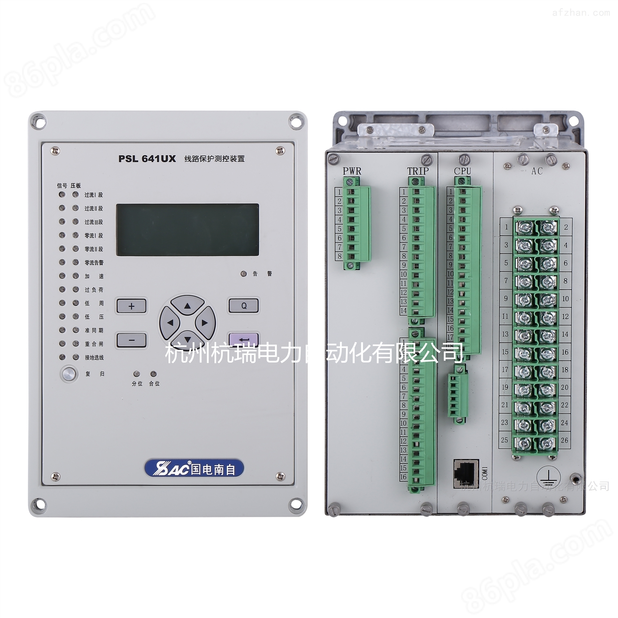
The PSC641UX capacitor protection device of Guodian Nanzi Comprehensive Protection is applicable to parallel capacitors with voltage levels of 35kV and below. The PSC 641UX capacitor protection measurement and control device is a multifunctional device that integrates various measurement and control functions, with current and voltage protection and unbalance protection as the basic configuration. The application areas cover industries such as power, water conservancy, transportation, petroleum, chemical, coal, metallurgy, etc.
Product Details
Guodian Nanzi Comprehensive Protection PSC641UX Capacitor Protection Device
1 Overview
1.1 Scope of Application
The PSC 641UX capacitor protection and measurement device is based on current and voltage protection and unbalance protection as the basic configuration, and integrates various measurement methods
A multifunctional device with quantity and control functions, suitable for parallel capacitors with voltage levels of 35kV and below. Application areas cover electricity, water conservancy, and transportation
Industries such as transportation, petroleum, chemical, coal, metallurgy, etc.
1.2 Protection Function Configuration
a) Two stage interphase current protection;
b) Two stage zero sequence current protection;
c) Overcurrent reverse time limit protection;
d) Zero sequence inverse time protection;
e) Undervoltage protection;
f) Overvoltage protection;
g) Three separate unbalanced protections;
h) Automatic switching function;
i) Non electricity protection;
j) TV disconnection discrimination.
1.3 Measurement and Control Function Configuration
a) Measurement quantities such as current, voltage, power, and power factor;
b) 14 channels of external switch input remote signal acquisition (larger 20 channels are optional);
c) Circuit breaker position, manual disconnection, and remote signaling for accidents;
d) Normal circuit breaker remote control opening and closing;
e) GPS timing input.
2 Protection functions and principles
Unless otherwise specified, the protection and automatic functions of the device are activated when the circuit breaker trips, and the output contacts "trip" (X3:1, X3:2) and standby are activated
1 (X3:8, X3:9), when the circuit breaker is closed, the output contacts are "closed" (X3:3, X3:4) and standby 2 (X3:11, X3:12). simultaneously
Output protection action signals (X4:1, X4:2).
2.1 Inter phase overcurrent protection
When the device performs two-stage overcurrent discrimination, the discrimination logic of each stage is consistent, and its operating conditions are as follows:
1) I >Idn, where Idn is the fixed value of n-segment current and I is the phase current;
2) T>Tdn, where Tdn is the fixed delay value for n segments.
2.2 Zero sequence overcurrent protection
When zero sequence current is used for tripping or alarm, the zero sequence current can be selected by the KG1.13 bit of control word one in the operating parameters
Introduced by external dedicated zero sequence CT or generated by software, the device defaults to zero sequence current external connection.
The implementation method of zero sequence overcurrent protection is basically the same as that of overcurrent components, and the outlet trips when the following conditions are met:
1) 3I0>I0n, where I0n is the fixed value of the grounding n-segment;
2) T>T0n, T0n is the fixed delay value for the n grounding segments.
For the transient period of this protection, when the zero sequence current 3I0 is greater than 1.5 times the fixed value of section I, the outlet trip time of the device shall not exceed 40ms.
2.3 Inverse time protection
Inverse time limit protection is a protective component that naturally matches the action time limit with the current in the protected capacitor. By translating the action curve, it can be used to protect the capacitor
Conveniently achieve full line coordination. The common analytical expressions for inverse time characteristics can be roughly divided into three categories: standard inverse time, extraordinary inverse time, and inverse time
Time limit, the inverse time limit characteristic in this device is set by the inverse time limit index in the set value.
2.4 Under voltage protection
Action conditions for undervoltage protection:
1) All three line voltages are below the undervoltage threshold;
2) The three-phase currents are all less than the current setting value;
3) Line voltage changes from high voltage to low voltage;
4) The circuit breaker is in the closed position;
5) Delay time is up.
Protect the exit action when the circuit breaker trips.
2.5 Overvoltage protection
When the following conditions are met, the overvoltage protection will activate:
1) Any line voltage is higher than the overvoltage setting value;
2) The circuit breaker is in the closed position;
3) Delay time is up.
Protect the exit action when the circuit breaker trips. When the control word KG1.0 is activated, the overvoltage protection voltage is taken from terminal X1:23-26 and wired
Connect the non-polar terminals of Unbalance 1 and Unbalance 2 to the B-phase voltage of the discharge coil, and connect the polar terminal of Unbalance 1 to the A-phase voltage of the discharge coil,
Unbalance 2 polarity terminal discharge coil C-phase voltage, at this time the device automatically exits unbalance 1 and unbalance 2 protection.
2.6 Unbalance Protection
The device provides three separate fixed values for unbalance 1, unbalance 2, and unbalance 3, and the unbalance can be voltage input or current input (specified)
Declaration at the time of shipment. The operating conditions are as follows:
1) Any unbalanced input greater than the corresponding unbalanced setting value;
2) The circuit breaker is in the closed position;
3) Delay time is up.
Protect the exit action when the circuit breaker trips. When the control word KG1.0 is activated, the device automatically exits the unbalanced 1 and unbalanced 2 protection.
2.7 Automatic switching function
When not using voltage reactive power regulation devices (such as VQC), users can choose this function according to the situation.
2.7.1 Automatic Removal Conditions
1) Any one of the three line voltages is greater than the self switching overvoltage setting value;
2) No protective action locking signal, terminal X2:1 has no input locking signal;
3) The circuit breaker is in the closed position;
4) Delay time is up;
5) Automatic feeding and cutting of pressure plates.
Guodian Nanzi Comprehensive Protection PSC641UX Capacitor Protection Device

