-
E-mail
125854791@qq.com
-
Phone
13931762407
-
Address
Botou City, Hebei Province
Product Categories
Botou Beihong Pump Manufacturing Co., Ltd

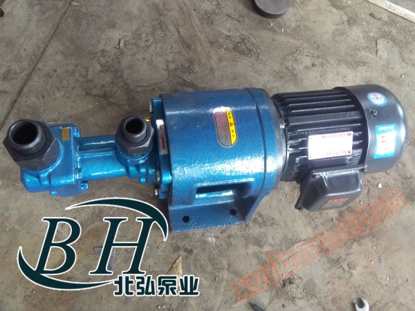
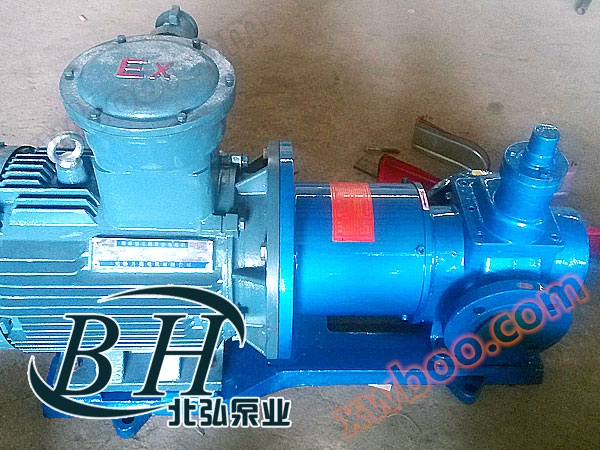
3GN Three Screw Pump
NegotiableUpdate on 11/30
- Model
- Nature of the Manufacturer
- Producers
- Product Category
- Place of Origin
Overview
1. Simple structure: It has multiple structural forms, generally with a small flow rate of 0.2~6.5m3/h. The pump body and liner are integrated into one (collectively referred to as the pump body), and the shaft seal is a mechanical seal
Product Details

1. Simple structure: It has multiple structural forms, generally with a small flow rate of 0.2~6.5m3/h. The pump body and liner are integrated into one (collectively referred to as the pump body), and the shaft seal is a mechanical seal. The liner of pumps with medium or higher flow rates is fixed as a separate part inside the pump body, while high flow pumps are often made with a double suction structure and installed horizontally. The shaft seal has two types: mechanical seal and packing seal, depending on the conveying medium. There are two installation forms for marine pumps: horizontal and vertical. The prime mover is an AC/DC marine electric motor.
2. Long service life: The active screw of the three screw pump is driven by an electric motor, and there is no mechanical contact between the main and auxiliary rods. The auxiliary rod rotates around the axis driven by the pressure liquid being transported. There is a layer of oil film protection between the main and auxiliary rods, and between the screw and the liner, so the mechanical friction of the pump is minimal and the service life is long.
3. The 3GN three screw pump has high suction capacity, and the conveyed liquid undergoes axial uniform linear motion inside the pump, with small pressure pulsation, stable flow rate, and low noise. Due to the small inertia of the rotating components, the starting torque and vibration are very small.
4. To ensure the safety of pumps, motors, and piping systems, screw pumps with medium flow rates and above are equipped with safety valves. When the pressure exceeds the set pressure of the safety valve, high-pressure oil will flow back to the inlet of the pump.
Precautions for Operation of 3GN Three Screw Pump
Kind Reminder
Dear customer, in order to ensure the good service life and performance of the product, please follow the following principles in product selection, configuration design, and maintenance:
1. The diameter configuration of the inlet and outlet pipelines must be consistent with the inlet and outlet diameter of the pump, and the diameter configuration of the pipelines must ensure that the vacuum degree of the pump is within the performance range during start-up and operation.
To avoid causing cavitation and air pockets, which can lead to abnormal vibration and noise of the pump, and even pump jamming.
2. It is strictly prohibited to idle without a medium, and the working medium must be added before use.
The three screw pump relies on the protective effect of the oil film of the medium between the rotating screw and the liner If there is an empty transfer, it will intensify the wear of the screw and liner.
3. It is strictly prohibited for any impurities, not limited to welding slag, to enter the pump chamber.
The three screw pump has a compact structure, and the screw and liner are tightly matched No gaps Impurities or welding slag in the medium can cause the pump card assembly or motor to burn out.
4. It is strictly prohibited to use Y-shaped filter devices. The inlet of the pump must be equipped with a bucket filter or a blue filter, and the unfolded filtering area of the filter mesh must not be less than 20-40 times the cross-sectional area of the pump inlet The filter of the pump is generally 20.40.60.80 mesh.
The 20 mesh filter medium is generally a relatively viscous medium such as asphalt Heavy oil Fuel Residual oil and waste oil.
The medium for a 40 mesh filter is generally Lubricating oil. Hydraulic oil. gear oil.
The medium for a 60 mesh filter is generally turbine oil Transformer oil Turbine oil. Thin oil.
The 80 mesh filter medium is generally thin and non lubricating, such as diesel Aviation kerosene Cooling oil Gasoline Rinse the oil.
5. If the installation position of the pump is above the liquid level, please carefully consider the pump's cavitation allowance, self-priming capacity, and correct piping configuration to ensure that the pump's performance meets the requirements of the operating conditions.
The cavitation allowance and self-priming height of the pump are both limited Generally, the larger the helix angle, the better the self-priming ability of the pump Please contact the manufacturer for specific data.
Important instructions on the selection and configuration of three screw pump units and precautions for use and start-up
1. It is strictly prohibited to idle without any medium. Before starting the vehicle, please be sure to add lubricating medium or conveying medium.
2. It is strictly prohibited for any debris, welding slag, etc. to enter the pump chamber, and the cleanliness of the pump chamber and pipeline interior must be maintained.
3. It is strictly prohibited to use pipeline filters or Y-shaped filter devices. Install filters to ensure that the filtering area is 20-30 times the cross-sectional area of the pump inlet diameter. And correctly configure the mesh size of the filter screen based on the cleanliness of the medium.
4. It is strictly prohibited for the inlet and outlet pipelines of the pump to be mismatched with the inlet and outlet pipelines of the pump. The pipe diameter configuration must be consistent with the inlet and outlet diameter of the pump. To prevent cavitation or inability to self suction. A thin pipeline will inevitably lead to cavitation, causing the pump to operate in a state of insufficient capacity, resulting in a decrease in flow and pressure of the three screw pump group, and even abnormal vibration and noise. Long term operation will also cause serious damage to the pump and screw pump.
5. The installation height of a three screw pump must fully consider the cavitation conditions of the pump and the self-priming capacity of the pump (the cavitation allowance is related to the viscosity and speed of the medium and the lead of the screw).
6. Due to the effects of packaging, transportation, lifting and unloading, as well as the tightening of pipeline bolts, the original factory positioning of the pump may change or even be severely misaligned. Therefore, after the installation and fixation of the three screw pump piping system, it is necessary to recheck the coaxiality of the three screw pump and motor before starting and driving.
7. It is strictly prohibited to start the machine with back pressure and close the inlet and outlet valves.
8. It is strictly prohibited to start rotation in a direction that does not comply with the pump rotation label.
9. Double pumps in parallel must be equipped with one-way valves at the outlet and inlet of the pump to prevent the medium from flowing back and driving the three screw pump to reverse.
10. It is strictly prohibited to adjust the safety valve bolts arbitrarily. The safety valve is only used to protect the safety of the pump and match the motor power with the working state of the pump. It is strictly prohibited to use it as a pressure regulating valve and overflow valve.
Performance parameters of three screw pump
| model | Discharge pressure P MPa |
Traffic Q | Speed n r/min |
Required cavitation allowance rm | Efficiency η% | electric motor | ||
| m3/h | L/min | Power kw | model | |||||
| 25×4-46 | 1.0 | 0.8 | 13 | 1450 | 4 | 62 | 0.75 | Y802-4 |
| 2.5 | 0.6 | 10 | 60.6 | 1.5 | Y90L-4 | |||
| 1.0 | 2.0 | 33 | 2900 | 4.5 | 59.4 | 1.5 | Y90S-2 | |
| 2.5 | 1.6 | 26 | 69 | 3 | Y100L-2 | |||
| 30×4-46 | 1.0 | 1.6 | 26 | 1450 | 4.5 | 63.5 | 1.1 | Y90S-4 |
| 2.5 | 1.2 | 20 | 61 | 2.2 | Y100L1-4 | |||
| 1.0 | 3.6 | 60 | 2900 | 5 | 60 | 2.2 | Y90L-2 | |
| 2.5 | 3.2 | 53 | 69 | 4 | Y112M-2 | |||
| 36×4-46 | 1.0 | 2.8 | 46 | 1450 | 4.5 | 66 | 2.2 | Y100L1-4 |
| 2.5 | 2.4 | 40 | 66.5 | 4 | Y112M-4 | |||
| 1.0 | 6.5 | 108 | 2900 | 5 | 60.5 | 4 | Y112M-2 | |
| 2.5 | 6 | 100 | 72 | 7.5 | Y132S2-2 | |||
| 42×4-46 | 1.0 | 4.8 | 80 | 1450 | 5 | 62 | 4 | Y112M-4 |
| 2.5 | 4.2 | 70 | 73 | 5.5 | Y132S1-4 | |||
| 1.0 | 10.5 | 175 | 2900 | 5.5 | 61 | 5.5 | Y132S1-2 | |
| 2.5 | 10 | 166 | 72 | 15 | Y160M2-2 | |||
| 45×4-46 | 1.0 | 6.3 | 106 | 1450 | 5 | 70 | 3 | Y100L2-4 |
| 2.5 | 5.9 | 99 | 74 | 7.5 | Y132M-4 | |||
| 1.0 | 13.5 | 225 | 2900 | 5.5 | 60 | 7.5 | Y132S2-2 | |
| 2.5 | 13 | 217 | 75 | 15 | Y160M2-2 | |||
| 60×4-46 | 1.0 | 15.5 | 255 | 1450 | 5 | 71.3 | 11 | Y160M-4 |
| 2.5 | 14.5 | 245 | 74 | 15 | Y160L-4 | |||
| 1.0 | 32 | 533 | 2900 | 5.5 | 63 | 18.5 | Y160L-2 | |
| 2.5 | 31.5 | 525 | 77 | 37 | Y200L2-2 | |||
| 70×2-46 | 0.6 | 24 | 400 | 1450 | 5 | 71 | 7.5 | Y132M-4 |
| 1.0 | 23.5 | 390 | 75 | 11 | Y160M-4 | |||
| 1.6 | 22.5 | 370 | 76 | 15 | Y160L-4 | |||
| 70×4-46 | 1.0 | 24.5 | 408 | 1450 | 5 | 72.5 | 18.5 | Y180M-4 |
| 2.5 | 23.5 | 392 | 79 | 30 | Y200L-4 | |||
| 80×2-46 | 0.6 | 36.5 | 608 | 1450 | 5 | 72 | 11 | Y160M-4 |
| 1.0 | 35 | 594 | 75.5 | 18.5 | Y180M-4 | |||
| 1.6 | 34.5 | 575 | 76.5 | 22 | Y180L-4 | |||
| 80×4-46 | 1.0 | 37 | 617 | 1450 | 5.5 | 72 | 30 | Y200L-4 |
| 2.5 | 35 | 590 | 78.1 | 45 | Y225M-4 | |||
| 100×2-46 | 0.6 | 72.5 | 1208 | 1450 | 5 | 73 | 22 | Y180L-4 |
| 1.0 | 71 | 1183 | 77 | 37 | Y225S-4 | |||
| 1.6 | 60.5 | 1158 | 79 | 45 | Y225M-4 | |||
| 100×4-46 | 1.0 | 72.5 | 1208 | 1450 | 5.5 | 73 | 55 | Y250M-4 |
| 2.5 | 70 | 1165 | 78.5 | 75 | Y280S-4 | |||
| S100×3-27 | 0.6 | 72 | 1196 | 1450 | 6 | 62 | 22 | Y180L-4 |
| 1.6 | 70 | 1160 | 72 | 55 | Y250M-4 | |||
| 2.5 | 69 | 1145 | 74 | 75 | Y280S-4 | |||
| S120×3-27 | 0.8 | 123 | 2055 | 1450 | 6 | 74.5 | 55 | Y250M-4 |
| 1.5 | 120 | 2010 | 76 | 90 | Y280M-4 | |||
| 2.5 | 115 | 1920 | 78.5 | 132 | Y315M-4 | |||